
Installation and Operation Manual

8
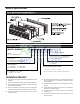
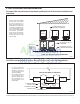
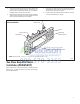
Figure 9
Dimensions
FRP007
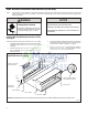
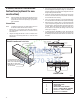
NOTE: The Wall Sleeve must be
horizontally level (side-to-side)
and pitched 1/4 bubble to the
outside when installed in an
opening.
The mounting hole location
should be approximately 2-4”
from the top and bottom of the
sleeve.
MOUNTING
HOLES
PLASTIC ANCHORS
WOOD SCREW
ALTERNATE
FASTENING METHODS
(Field Supplied)
TOGGLE BOLT
EXPANSION
ANCHOR BOLT
SCREWS
WALL
SLEEVE
Figure 8
Wall Sleeve Attachment
FRP009
¼"
13-¾"
A
C
B
Dimension*
AB
Allow
for floor
finishing
Allow
for wall
finishing
(Minimum)Min. Max.
No Accessories
¼"
MIN.
WALL
¼"
---
With Subbase 1-¾" 3-½" 5"
With Lateral Duct ¾"
C
Allow
for proper
drainage
(Front-to-Back)
¼"
---
---
---
---
* If more than one accessory is to be used, use the maximum
dimension. If the wall thickness is more than 13-¾" - (A+ ¼"),
a sleeve extension must be used.
Wall Sleeve Tilt ¼"
---------