
Product Profile


11
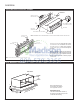
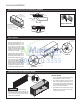
Architectural Louver Installation (PXAA)
INSTALLATION
1. Screw a threaded metal stud into each of the
holes at the four corners of the louver.
2. From inside the building, grasp the louver
at the vertical supports and maneuver the
louver through the wall sleeve. Pull towards
you until the threaded studs are inserted into
the four holes of the wall sleeve.
3. While holding the louver with one hand, start
washers and nuts on each of the four studs.
Tighten the nuts securely.
External Drain
PXDR10 DRAIN KIT
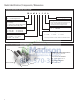
Internal Drain Kit Location and Installation (PXDR10)
Accessory Installation
When using an external drain sys-
tem, the condensate is removed
through either of two drain holes
on the back of the wall sleeve.
Select the drain hole which best
meets your drainage situation and
install the drain kit. Seal off the
other with a cover plate.
Place the drain tube through the
gasket and the mounting plate with
the ange toward the wall sleeve.
Attach the drain tube assembly to
one of the two drain holes at the
rear of the wall sleeve. The large
ange on the mounting plate is po-
sitioned at the bottom of the sleeve
facing toward the sleeve. When
the drain tube is positioned at the
desired angle, tighten the screws.
CAUTION
Bodily injury can be caused by louvers
falling from a building during installation. It is
recommended that a safety line be attached
to the louver and an anchor point inside the
building during installation.
FRP011
DRAIN TUBE
SIDE VIEW
FRONT VIEW
WALL SLEEVE
OPTIONAL AREA
PREFERRED AREA-
NO FOAM INSULATION
IF
THE DRAIN MUST BE
LOCA
TED IN THE OPTIONAL
A
REA, THE FOAM INSULATION
MUST
BE CUT AWAY AND
REMOVED
TO ALLOW ACCESS
TO
THE DRAIN.
NUT
MOUNTING
PLATE
GASKET
SCREW
3"
FRP012
FOAM
GASKET
OVERFLOW
SLOTS
DETAIL B
DETAIL A
COVER
PLATE
FOAM
GASKET
SCREWS
½” O.D. TUBE
MOUNTING
PLATE
NUT