
Product Profile


12
HVAC Engineering Specifications
Digital Packaged Terminal Air Conditioners & Heat Pumps
All units shall be factory assembled, piped, wired and fully charged
with R-410A. All units shall be certied in accordance with ARI Stan-
dard 310 for air conditioners and ARI standard 380 for heat pumps.
Units shall be UL listed and carry a UL label. All units shall be factory
run-tested to check operation and be Friedrich or equivalent.
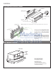
The basic unit shall not exceed 16” high x 42” wide. Overall depth of
the unit from the rear of the Friedrich wall sleeve to the front of the
decorative front cover shall not exceed 21 ¼”. The unit shall be de-
signed so that room intrusion may be as little as 7 ½”. Installations in
walls deeper than 13 ¼” may be accomplished with the use of a deep
wall sleeve (PDXWSEXT). Unit shall draw in ambient air through both
sides of an outdoor architectural louver or grille measuring 42” wide
x 16” high and shall exhaust air out middle portion of the louver. The
architectural louver and wall sleeve shall be designed so that the
louver may be installed from the inside of the building.
REFRIGERATION SYSTEM – The refrigeration system shall be her-
metically sealed and consist of a rotary compressor that is externally
mounted on vibration isolators no smaller than 1 3/8” dia. x 1 ½” high;
condenser and evaporator coils constructed of copper tubes and
aluminum plate ns; and capillaries as expansion devices. Unit shall
have a fan slinger ring to increase efciency and condensate disposal
and have a drain pan capable of retaining 1 ½ gallons of condensate.
A tertiary condensate removal system shall also be incorporated for
back up and shall overow through the wall sleeve and to the outside
of the building as a safeguard against damage to the interior room.
INDOOR AIR HANDLING SECTION – The indoor air handling section
shall consist of a tangential blower wheel direct driven by a totally en-
closed mo
tor. The air handling system shall be designed to minimize
airflow noise and provide smooth and consistent airflow. The indoor fan
must have two fan speeds that may be selected by the user.
The indoor discharge grille shall be designed to maximize airow
throughout the room. The grille shall be reversible to allow a change
in the air ow directions. The grille openings shall be sized to prevent
personal injury or damage to the unit.
The front cover shall incorporate dual air lters conveniently mounted
in the front of the unit. The lters must be accessible without the
removal of the front cover. The lters shall be made of anti-microbial
material to prevent mold and bacterial growth. The lters shall be
washable and reusable by cleaning with water or by vacuuming.
The chassis shall have a built-in damper capable of providing at least
75 CFM of fresh air into the conditioned area. A ne mesh screen shall
lter the incoming fresh air. There must be a provision for locking
the damper closed to ensure a proper seal.
OUTDOOR AIR HANDLING SECTION – The outdoor air section shall
consist of a single injection molded fan shroud that incorporates the
outdoor motor mount into a single piece for ease of service and as-
sembly. The outdoor motor shall be totally enclosed, ball-bearing,
permanently lubricated and directly drive the outdoor fan/slinger ring.
CONTROLS – Covered controls shall be accessible in a compartment
at least 7½” wide with the controls no deeper than 1 ¼” in the opening
to facilitate easy operation of the unit.
The unit controls shall feature a soft blue LED readout that can
display either room temperature or setpoint temperature. The unit
shall receive input from the digital control panel through push but-
tons labeled: ‘Cool’, ‘Heat’, ‘High Fan’, ‘ ‘Low Fan’, ‘ ,’
’ and
‘Power’.
When ‘Off’, the unit may be put directly into cooling or
heating mode by pressing the ‘Cool’ or ‘Heat’ button.
The unit must have the following energy saving and convenience
features built-in:
• Quiet start/stop fan delay
• Fan cycle control for cooling and heating independently
• Room freeze protection
• Random compressor restart
• Electronic temperature limiting
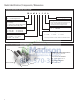
The PTAC must also offer the ability to be controlled by a remote
wall-mounted thermostat without additional accessories. Low volt-
age inputs will include: C (common), R (24V power), Y (cooling), GL
(fan low), GH (fan high), W (heat) and O (reversing valve on PDH heat
pumps only).
PTAC models shall use a single stage cool / single stage heat ther-
mostat. PTHP models shall use a single stage cool / two-stage heat
thermostat. An accessory thermostat must be available from the
manufacturer, RT6 or equivalent. The RT6 thermostat will provide
temperature setpoint, mode selection from cool, heat and fan modes.
The thermostat must also allow the selection of fan speed between
high and low speed.
Other controls accessible without removal of the chassis shall include
fan cycle switch, fresh air vent control and emergency heat override
switch (heat pump only).
ELECTRICAL CONNECTION – All PTAC/PTHP units shall come from
the factory with a power cord installed. All 230/208V power cords shall
feature a leakage current detection device on the plug head. All units
shall feature a 6-pin connector for removal of the power cord. The
power cord shall be interchangeable to allow changes to the heater
output based on the property/electrical requirements.
GENERAL CONSTRUCTION – The wall sleeve shall be constructed
of 18-gauge Galvanized zinc-coated steel. It shall be prepared by
a process where it is zinc phosphate pretreated and sealed with a
chromate rinse, then powder coated with a polyester nish and oven
cured for durability. The sleeve shall be shipped with a protective
weatherboard and a structural center support, and be insulated for
sound absorption and thermal efciency. The grille or louver shall
be shipped separately and made from stamped or extruded anodized
aluminum. All louvers shall be in the horizontal plane.
The front panel shall attach rmly to the chassis by t wo hidden spring
clips. As an option the cover may be attached by two screws to prevent
tampering. The front panel will feature a contoured discharge with
no sharp corners.
CORROSION PROTECTION – The unit shall have corrosion-resistant
fans, fan shroud and drain pan for corrosion protection and to pre-
vent rust on the side of the building below the outdoor louver. The
unit shall feature corrosion resistant materials and nishes to help
prevent deterioration. The outdoor coil shall have Diamonblue cor-
rosion protection consisting of hydrophilic coated ns to prolong the
life of the coil in all applications including seacoast environments. All
outdoor coils shall also have stainless steel endplates to eliminate
rusting of the endplates.
WARRANTY – The warranty is two years on all parts and labor and 5
years on the sealed system, parts and labor, including compressor,
indoor and outdoor coils and refrigerant tubing.
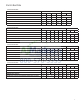
Cooling: 7000 – 14500 Btu
Heating: 5800 – 13300 Btu (Heat Pump)
6800 – 17000 Btu (Electric Heat)
Friedrich Models: PDE – Cooling with or without electric heat
PDH – Heat Pump with electric heat