
Installation and Operation Manual (2019, 2020, 2021)

HOW TO ENTER
• Set thermostat to OFF mode
• Hold UP + FAN for 5 seconds
HOW TO NAVIGATE
• Press UP or DOWN to change setting value
• Press MODE to save setting value and proceed to next setting option
• Press FAN to return to previous setting option
HOW TO EXIT
• Press MODE until last setting page (99) has been saved or leave thermostat with no button press
for 60 seconds
• Note: You must press MODE to save each setting value
INSTALLER SETTINGS
CHANGING MODE
• Press MODE button to initiate mode selection menu
• Press MODE button until desired system mode is blinking. After 2 seconds of no button press
desired mode is selected
CHANGING SET TEMPERATURE
• Ensure thermostat is in correct system mode (Heat, Cool or Auto)
• Press UP or DOWN button. New set temperature will be displayed in large digits. After 2 seconds
of no button press new set temperature is selected
• If Programming mode is OFF,thennewsettemperaturewillbeheldindenitely.Ifprogrammingmode
is ON (see below), then new set temperature will be held until next scheduled set-point change
CHANGING FAN SPEED
• Press FAN button to initiate fan speed selection menu
• Press FAN until desired fan mode is selected. After 2 seconds of no button press desired fan
mode is selected
• AUTO: fan operates as needed during a call for heating or cooling activation only.
• LOW:fanoperatescontinuouslyinlowspeed.Heat/Coolwillturnon/oinbackgroundasneeded.
• HIGH:fanoperatescontinuouslyinhighspeed.Heat/Coolwillturnon/oinbackgroundasneeded.
SETTING A KEYPAD / FRONT PANEL LOCKOUT
• While in any normal operating mode except OFF, a keypad lockout can be introduced which
will prevent any mode change, fan change or temperature adjustment from being made by the
user. Even when locked, any button press will illuminate the display backlight.
• To activate (and deactivate) the keypad lockout, set thermostat to heat, cool or auto mode then
hold FAN + UP buttons for 5 seconds. When the keypad is locked, a padlock will appear in the
lower left corner of the display.
SET CLOCK AND TEMPERATURE PROGRAM SCHEDULE
• NOTE: After 60 seconds with no button presses thermostat will exit the settings menu
• Set thermostat to OFF mode and hold MODE + UP buttons for 5 seconds. From this point you
have the following options
• Set thermostat real-time clock
• Set a heat schedule
• Set a cool schedule
• Use UP or DOWN buttons until desired section is blinking. Press MODE to enter selection.
• To exit press FANorselect“Exit”andpressMODE
ADJUSTING THE REAL-TIME CLOCK
• Once the real-time clock menu has been selected use the UP or DOWN buttons to set each
variable. MODE will save value and proceed to next variable. FAN will return to prior variable.
• By default, the thermostat will automatically adjust the clock for Daylight Savings. This can be
disabled by changing the Auto Daylight Savings (setting 16) option in the installer menu
ADJUSTING THE HEAT OR COOL TEMPERATURE PROGRAM
• NOTE: Each period ends at the start time of the next upcoming period.
• NOTE:Ifconguredtouseonly2periods,onlyDAY and NIGHT will be used, and the MORN
and EVEN periods will not be used or visible. If you use 1 period and 7 day programming, then
thermostat will reset to the desired set temperature at the same time each day.
• Once either HEAT or COOL programming sections has been selected, choose which day[s] to
schedule together (i.e. all weekdays together, or each day separately). Use the UP or DOWN
buttons to scroll through the blinking days and press the MODE to select each day with a
indicator dot. Press FAN to deselect any previously selected day. Once all desired days are
selected,moveblinkingselectionto“SCHED”andpresstheMODE button to proceed.
• AdjustthestarttimeoftherstperiodusingUP or DOWN buttons and press the MODE button.
Press the UP or DOWNbuttonstosetthedesiredtemperaturefortherstperiod.Pressthe
MODE button to continue to the next period.
• Repeat until all periods have been set. Thermostat will return to day selection page.
• Ifalldesireddayshavebeenscheduledselect“EXIT”andpressMODE. Otherwise use the UP
and DOWN buttons to move blinking selection to desired days and press MODE to select day[s]
for scheduling.
ENTERING EMERGENCY HEAT MODE (HP UNITS ONLY)
• While in HEAT mode, press DOWN + MODE for 5 seconds. The thermostat will show HEAT with
“E”toconrmEmergencyHeatmode.ThiswilluseonlytheW2wireastheheatingsourceand
will not call for compressor heating.
• To return to normal heating mode, set thermostat to HEAT mode, press and hold BOTH the
MODE and DOWNbuttonsforatleast5secondsuntilthescreenchanges.The“E”willdisappear
andonlyshow“HEAT”toconrmregularHeatmode.
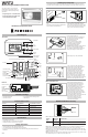
• The RF icon in the top right corner of the LCD shows the RF connection state between
transmitter and receiver.
• BLANK: No receiver paired
• SOLID: Transmitter and receiver connected
• FLASHING: Receiver paired but disconnected
• Whenyourstpowerupatransmitterandreceivertheywillbeinpairingmodefor10minutes.If
you need to start the pairing process after this timeframe, follow these steps:
NORMAL OPERATION
Menu
Number
Function Description User Option Number Default
setting
19 Default heat mode set temperature
(manual mode only)
60°F to Max Heat Set Temp 70°F
20 Default cool mode set temperature
(manual mode only)
Min Cool Set Temp to 80°F 74°F
21 Start RF Pairing NO: no action
YES: start RF pairing
DEL: delete the current receiver
INFO: show RF status for receiver
NO
98 Minimumotime-
Compressor protection
NO:Immediateo/onswitching
YES:3-minuteminimumotimeenforced
NO
99 Reset NO: no reset
YES: ex-factory reset
NO
Note 1: If connecting to a Cool only PTAC unit, the W1 and W2 wires will not be used and Installer
Settingsmenu03(AvailableModes)shouldbesetto“04:CoolOnly”
Note 2:ForPTACunitswithonlyonefanspeed(single“G”fanterminal),usethe“GL”wireforwiring
andInstallerSettingsmenuItem12(HighFan)mustbesetto“OFF”.
WIRING DIAGRAM: Heat - Cool
RF PAIRING
Menu
Number
Function Description User Option Number Default
setting
01 Temperature Scale F: Fahrenheit
C: Celsius
F
02 Temperature Calibration +/- 5.4°F 0.0°F
03 Available modes 01 : Heat and Cool with auto
02 : Heat and Cool without auto
03 : Heat only
04 : Cool only
01
04 Max Heat Set Temp F: 60 to 90 (5°F step) 80°F
05 Min Cool Set Temp F: 60 to 80 (5°F step) 65°F
06 PTAC Type H-C: Heat-Cool
HP: Heat Pump
H-C
07 HP valve type B: B Valve
O: O Valve
B
08 Auto dead-band between heat and
cool operation in AUTO mode
2 to 5°F (1°F step) 4°F
09 Stage 1 Temperature Control Swing ±0.25°F
±0.50°F
±1.00°F
±2.25°F
0.50°F
10 AuxiliaryStageCut-InOset(only
used for HP system type)
OFF (No Electric / Auxiliary heat)
-3.0 to -8.0°F (1°F step)
-4.0°F
11 (Not Used)
12 High FAN availability ON: High fan available
OFF: High fan not available
ON
13 Programming mode OFF: Manual
ON: Programmable
OFF
14 Clock Format
(Programming mode only)
12 : 12 hour
24 : 24 hour
12
15 Periods per day
(Programming mode only)
4: 4 periods per day
2: 2 periods per day
1: 1 period per day
2
16 Auto Daylight Savings
(Programming mode only)
ON: Auto DST on
OFF:AutoDSTo
ON
17 (Not Used)
18 Reset to default set temperatures
after each mode change (manual
mode only)
ON: uses default temperatures after each mode
change (see menu 19 and 20)
OFF: Maintain last set temperature for each mode
ON
Friedrich Air Conditioning Co.
10001 Reunion Pl Suite 500,
San Antonio, TX 78216
1-877-599-5665
www.friedrich.com
W
Y
GH
GL
C
R
R
W1
Y
GH
GL
C
1. AttheReceiver,useasmallatheadscrew
driver to open the grey front cover. Hold down
the RF Pairing button for 5 seconds until the
BlueRFindicatorLEDstartstoash.
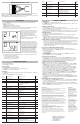
2. At the Transmitter put thermostat in OFF
mode and hold FAN and DOWN buttons for
10 seconds.
3. When the screen says ‘YES’ press the MODE
button to start scanning process.
4. After scanning, the display will show the ID
and RSSI signal strength of any receivers it
has found. Match the receiver ID with the label
found inside the receiver housing near to the
RF Pairing button. If more than 1 receiver has
been found, use the UP and DOWN buttons
to select the desired Receiver. Press MODE to
conrmselectionorpressFANtogoback.
5. If needed, steps 3 & 4 may be repeated to
checksignalstrengthindierentlocations.
A signal strength between 40 and 70 is
recommended. A signal strength between 85
and 100 may lead to connectivity problems.
SETTINGS
SETTINGS
• Ifthethermostatisexperiencingconnectivityissuesoryoundasignalstrengthof85to100
during pairing, please try the following:
• Move the transmitter closer to the PTAC
• Re-orientate the receiver within the PTAC
• Place the receiver outside of the PTAC
Receiver ID RSSI Signal Strength
FCC Statement
This device complies with part 15 of the FCC Rules. Operation is subject to
the following two conditions:
(1) This device may not cause harmful interference, and
(2) this device must accept any interference received, including interference
that may cause undesired operation.
Changesormodicationsnotexpresslyapprovedbythepartyresponsiblefor
compliance could void the user's authority to operate the equipment.
NOTE: This equipment has been tested and found to comply with the
limits for a Class B digital device, pursuant to part 15 of the FCC Rules.
These limits are designed to provide reasonable protection against harmful
interference in a residential installation.
This equipment generates, uses and can radiate radio frequency energy
and, if not installed and used in accordance with the instructions, may cause
harmful interference to radio communications. However, there is no guarantee
that interference will not occur in a particular installation.
If this equipment does cause harmful interference to radio or television
reception,whichcanbedeterminedbyturningtheequipmentoandon,the
user is encouraged to try to correct the interference by one or more of the
following measures:
•Reorient or relocate the receiving antenna.
•Increase the separation between the equipment and receiver.
•Connecttheequipmentintoanoutletonacircuitdierentfromthatto
which the receiver is connected.
•Consult the dealer or an experienced radio/TV technician for help.
Thisdevicemustbeusedinxedlocationsandinsuchawaythata
separation distance of at least 20 centimeters is normally maintained
between the transmitter's radiating structure(s) and the body of the user or
nearby persons.
IC Statement
This device complies with
Industry Canada licence-
exempt RSS standard(s).
Operation is subject to the
following two conditions:
(1) this device may not cause
interference, and
(2) this device must accept
any interference, including
interference that may cause
undesired operation of the
device.
Le présent appareil est
conforme aux CNR d'Industrie
Canada applicables aux
appareils radio exempts
de licence. L'exploitation
est autorisée aux deux
conditionssuivantes :
(1) l'appareil ne doit pas
produire de brouillage, et
(2) l'utilisateur de l'appareil
doit accepter tout brouillage
radioélectrique subi, même si
le brouillage est susceptible
d'en compromettre le
fonctionnement.