
Manual


920-087-02(9-03)
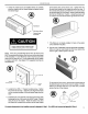
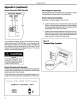
4. Center the chassis in the pre-instaned sleeve and carefully
push the chassis untilthe chassis flange and gasket contact
the sleeve flange.
®
....... Wall sleeve
Wallsleeveflange
Chassisflange
and gasket
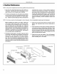
at the bottom back corners of the cover. Tighten them into
the quick nuts located on the chassis to secure the cover. If
the unit has been placed such that there is no room to insert
the thumbscrews from the bottom, request a Side Mounting
kit (Part No. PXSM) from Friedrich. Locate the service cord
or conduit in the notch at the bottom right of the front cover.
®
NOTE: If the unit is mounted flush to the floor, the service cord
MUST bereroutedat the bottom of the frontcoveron the sideclosest
to the receptacle. A notch MUST be made in the front cover side
where the cord exits the unit. Itis the responsibility of the installer
to create an exit notch. See diagram 8 for suggested opening size
and placement.
®
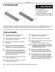
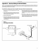
mounting screw
Chassis
flange
5. Locate the four #10 x 1" chassis mounting screws. Tighten
the screws into the clips - adjacent to the alignment dimples
on the mounting brackets on the wall sleeve flange (two per
side).
6. lnstanthe frontcover assembly (including the dischargegrine)
by placing the top of the cover onto the 90° angle bracket
along the top of the chassis. Rotate the bottom into place
and insert the included thumb screws into the slots located
7. If the filters are not already installed in tracks in the plastic
cover, slide them into place.
8. Plug the cord (if applicable) into the appropriate receptacle.
Extra cord may be coiled inside the front cover behind the
return air grille. Restore power to the unit.
®
To remove the front cover, remove the thumbscrews at
the bottom back comers of the cover (or sides). Pull the
bottom end forward and lift it up to clear the L bracket
across the top of the chassis.
®
Not to scale
If a remotethermostat isto be installed,proceedtoAppendixA,Step 1. Fora 265 Vunit, proceedto AppendixB,Step 1. 13