
Manual


920-087-02(9-03)
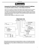
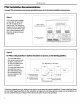
Wall SleeveInstallation Instructions(PXWS)
NOTE: Insurethat the unit is only installed inawall structurally adequate to support the unit includingthe sleeve,chassis and accessories.
Ifthe sleeve projects more than 8" intothe room, a subbase or other means of support MUST be used. Please read these instructions
completely before attempting installation.
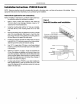
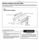
Figure 5
TypicalWall Sleeve Installation
Lintel to support masonry walls .--_.b_//_
10"
(25.4 cm
Electrical receptacle -
Wall opening Wall sleeve
/
1 1_ _ /]
41._m) _\_'[_ -- -- Electrical receptacle
Insulation --
Smoothsideof screw
slip facing into room
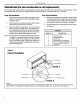
ForDeep Wall Installation See Section II
The following instructions apply ONLY to walls less than
13 1/4" in depth.
1. Frominside the building, positionthe wall sleevein the opening
and push itthrough the wall so it protrudes at least 1/4"on the
outside, note Figure 5.
2. Position the wall sleeve with a slight tilt towards the outside to
facilitate condensate drainage. It should be level side-to-side
and the front should be 1/4 bubble higher than the back. DO
NOT allow any pitch toward the inside.
Electricalshock hazard.
Turn electric power OFF at the fuse box or service panel
before making any electrical connections and ensure a
proper ground connection is made before connecting line
voltage. Failureto do so can result in property damage,
personal injury and/ordeath.