
Installation & Operation Manual (ZoneAire Series 2016 - 2020) (2016, 2017, 2018, 2019, 2020)
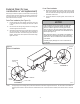
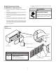
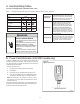
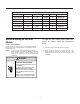
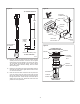
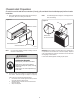
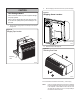
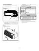
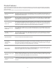
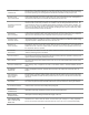
Table Of Contents
- Table of Contents
- Congratulations
- General Instructions
- WARNING
- Refrigeration system under high pressure
- WARNING
- Read Installation Operation Manual
- Your safety and the safety of others are very impo
- General Specifications
- Typical Unit Components and Dimensions
- Installation Checklist
- PTAC Installation Recommendations
- For proper PTAC unit performance and maximum opera
- For PTACs on the ground floor or anytime obstructi
- Wall Sleeve Installation Instructions (PDXWSA)
- WARNING
- Falling Object Hazard
- Alternate Wall Instalations
- One-Piece Deep Wall Sleeve Installation (PDXWSEXT
- PXDR10 Drain Kit Installation Instructions (option
- Internal Drain
- FRONT VIEW
- Drain Tube Installation (See Figure 12)
- Cover Plate Installation
- DETAIL B
- PXGA Standard Grille Insta lation Instructions
- WARNING
- Falling Object Hazard
- Electrical Rating Tables
- All units are equipped with standard power cords.
- Electrical Shock Hazard
- Power Cord Information (230/208V models only)
- Electrical Wiring for 265 Volt Models
- Power Cord Installation
- To install the line voltage power leads and condu
- Electrical Shock Hazard
- Chassis Install Preparation
- Check to be sure the wall sleeve, extension (if us
- Suffocation Hazards
- CAUTION
- Unit Damage Hazard
- Chassis Installation
- Excessive Weight Hazard
- System Configuration
- Fresh Air Vent Control
- Adjusting Air
- Backside of Front Panel
- Adjusting Louvers
- Digital Control User Input Configuration
- Dip Switch Setting
- Dip Switches
- Digital Control Operation
- Digital Control Panel
- °F vs °C Display
- Cooling Mode
- Heating Mode
- Heat Pump Models (PZH)
- Heat/Cool Models (PZE)
- Emergency Heat Operation
- Constand Fan
- Setting Temperature Limit
- Remote Control Thermostat Installation
- Install Thermostat
- The Thermostat should NOT be mounted:
- To control the unit with a wall mounted thermosta
- Thermostat Connections
- Control board with optional PDXRTB escutcheon kit
- Front Desk Control Terminal
- Energy Management
- Final Inspection & Start-up Checklist
- WARNING
- Decorative Front
- Fan Motor & Compressor
- Wall Sleeve
- Basic Troubleshooting
- Accessories
- PZ-SERIES

14
TABLE 2
MODEL
HEATER kW
Power Cord Kit
Voltage
Amperage
Receptacle
PZE / PZH07K
3.6
STD
230/208
20
NEMA 6-20r
PZE / PZH09K
3.6
STD
230/208
20
NEMA 6-20r
PZE / PZH12K
3.6
STD
230/208
20
NEMA 6-20r
PZE / PZH15K
5.0
STD
230/208
30
NEMA 6-30r
PZE / PZH09R
3.6
STD
265
20
NEMA 7-20r
PZE / PZH12R
3.6
STD
265
20
NEMA 7-20r
Electrical Wiring for 265 Volt
Models
Power Cord Installation
All 265V PTAC/PTHP units come with a factory installed non-LCDI
power cord for use in a subbase.If the unit is to be hard-wired refer to
the instructions below.
NOTE: It is recommended that the PXSB subbase assembly,the
PXCJA conduit kit (or equivalent) be installed on all hardwire
units.If installing a flush-floor mounted unit,make sure the
chassis can be removed from the sleeve for service and
maintenance.
To install the line voltage power leads and
conduit to chassis, follow the instructions
below.
1. Follow the removal process of the chassis’s junction box.
2.
Prepare the 265V(or 230V) power cord for connection to the
chassis’ power cord connector by cutting the cord to the
appropriate length.Power cord harness selection shown on Table
2 on page14.
WARNING
Electrical Shock Hazard
Turn off electrical power before service
or installation.
ALL electrical connections and wiring
MUST be installed by a qualified
electrician and conform to the National
Code and all local codes which have
jurisdiction.
Failure to do so can result in property
damage, personal injury and/or death.