
Installation & Operation Manual (ZoneAire Series 2016 - 2020) (2016, 2017, 2018, 2019, 2020)
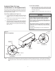
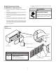
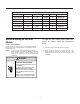
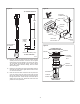
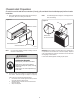
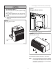
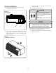
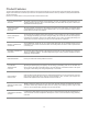
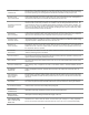
Table Of Contents
- Table of Contents
- Congratulations
- General Instructions
- WARNING
- Refrigeration system under high pressure
- WARNING
- Read Installation Operation Manual
- Your safety and the safety of others are very impo
- General Specifications
- Typical Unit Components and Dimensions
- Installation Checklist
- PTAC Installation Recommendations
- For proper PTAC unit performance and maximum opera
- For PTACs on the ground floor or anytime obstructi
- Wall Sleeve Installation Instructions (PDXWSA)
- WARNING
- Falling Object Hazard
- Alternate Wall Instalations
- One-Piece Deep Wall Sleeve Installation (PDXWSEXT
- PXDR10 Drain Kit Installation Instructions (option
- Internal Drain
- FRONT VIEW
- Drain Tube Installation (See Figure 12)
- Cover Plate Installation
- DETAIL B
- PXGA Standard Grille Insta lation Instructions
- WARNING
- Falling Object Hazard
- Electrical Rating Tables
- All units are equipped with standard power cords.
- Electrical Shock Hazard
- Power Cord Information (230/208V models only)
- Electrical Wiring for 265 Volt Models
- Power Cord Installation
- To install the line voltage power leads and condu
- Electrical Shock Hazard
- Chassis Install Preparation
- Check to be sure the wall sleeve, extension (if us
- Suffocation Hazards
- CAUTION
- Unit Damage Hazard
- Chassis Installation
- Excessive Weight Hazard
- System Configuration
- Fresh Air Vent Control
- Adjusting Air
- Backside of Front Panel
- Adjusting Louvers
- Digital Control User Input Configuration
- Dip Switch Setting
- Dip Switches
- Digital Control Operation
- Digital Control Panel
- °F vs °C Display
- Cooling Mode
- Heating Mode
- Heat Pump Models (PZH)
- Heat/Cool Models (PZE)
- Emergency Heat Operation
- Constand Fan
- Setting Temperature Limit
- Remote Control Thermostat Installation
- Install Thermostat
- The Thermostat should NOT be mounted:
- To control the unit with a wall mounted thermosta
- Thermostat Connections
- Control board with optional PDXRTB escutcheon kit
- Front Desk Control Terminal
- Energy Management
- Final Inspection & Start-up Checklist
- WARNING
- Decorative Front
- Fan Motor & Compressor
- Wall Sleeve
- Basic Troubleshooting
- Accessories
- PZ-SERIES

17
CAUTION
Unit Damage Hazard
Failure to follow this caution may result in equipment damage
or improper operation.
Failure to remove shipping tape and screw will prevent fresh
air vent door from opening and may result in damage to vent
door cable.
3. Carefully remove shipping tape from the front panel and vent door.
See Figure 20
4. Remove shipping screw from the vent door, if present. See Fig 21.
Figure 21
Shipping Screw Location
Figure 20
Shipping Tape Location
REMOVE SHIPPING
SCREW IF PRESENT
5. Remove front panel. See Figure 22.
Figure 22
Removing Front Panel
FRP020
FRP022
Pull out at the bottom to release it from the tabs (1). Then lift up (2).
NOTE: If the unit is mounted flush to the floor, the service cord MUST
be rerouted at the bottom of the front cover on the side closest
to the receptacle. A notch MUST be made in the front cover
side where the cord exits the unit. It is the responsibility of
the installer to create an exit notch.
FRP021
SHIPPING
TAPE
2
1