
Service and Parts Manual (2016, 2017, 2015)
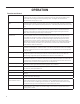
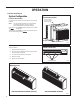
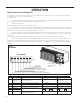

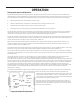
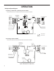
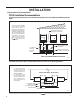
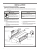
Table Of Contents
- INTRODUCTION
- Important Safety Information
- Personal Injury Or Death Hazards
- Operation of Equipment in During Construction
- Model Number Reference Guide
- Serial Number Reference Guide
- Product Features
- General Specifications
- 230V COOLING AND HEATING PERFORMANCE
- 265V COOLING AND HEATING PERFORMANCE
- Electric Heat Data
- Dimensions
- Electrical Data
- Function and Control
- Digital Control User Input Configuration
- Digital Control
- Refrigeration Sequence Of Operation
- Refrigerant System Diagram
- PTAC Installation Recommendations
- Wall Sleeve Installation Instructions (PDXWS)
- Alternate Wall Installations
- PXDR10 Drain Kit Installation
- External Drain
- PXGA Standard Grille
- Chassis Install Preparation
- Thermostat
- Final Inspection & Start-up Checklist
- Refrigerant Charging
- Undercharged Refrigerant Systems
- Overcharged Refrigerant Systems
- Restricted Refrigerant System
- Sealed System Method of Charging/ Repairs
- Electrical
- Hermetic Components Check
- Reversing Valve Description And Operation
- Testing The Reversing Valve Solenoid Coil
- Checking The Reversing Valve
- Touch Test Chart : To Service Reversing Valves
- Compressor Checks
- Compressor Replacement
- Compressor Replacement -Special Procedure in Case of Compressor Burnout
- Basic Troubleshooting
- Malfunction Analysis
- Troubleshootin Chart
- Heat Pump
- Remote Wall Thermostat Wiring Diagram
- Cool With Electric Heat
- Heat Pump With Electric Heat
- PZE
- PZH
- Reference Sheet of Celsius and Fahrenheit
- Resistance Table for Air Indoor Temperature Sensor
- Resistance Table for Frost Protection Indoor and Outdoor Temperature Sensors

23 PB
OPERATION
Digital Control User Input Conguration
22
The.adjustable.control.dip.switches.are.located.at.the.lower.left.hand.portion.of.the.digital.Smart.Center..The.inputs.are.only.visible.and.accessible.with.the.
front.cover.removed.from.the.PTAC.
Digital Control User Input Configuration
Switch Description Function Factory Setting Option
1 Emergency.Heat.Override.
for.PZH.Heat.Pump.
Models
Enables.electric.heat.only.operation.in.the.event.of.a.com-
pressor.failure.on.HP.models.
Down.-.Normal.Operation Up.-.Overrides.compressor.operation..
(PDH.models.only)
2 Wall.Thermostat.Switch Enables.the.use.of.a.wall.thermostat.or.unit.controls Down.-.Unit.Controls Up.-.Enables.Wall.Thermostat.Usage
3 Fan.Cycle.for.Heating Allows.selection.of.continuous.fan.or.cycling.in.heating.mode. Not. Applicable
4 Fan.Cycle.for.Cooling Allows.selection.of.continuous.fan.or.cycling.in.cooling.mode. Not. Applicable
Not. Applicable
Not. Applicable
5 Setpoint.Switch.1 Allows.the.temperature.setpoint.range.to.be.adjusted. Down
61ºF-86ºF
Up 63ºF-80ºF Down Up
6 Setpoint.Switch.2 Down (16ºC-30ºC) Down (18ºC-28ºC)
65ºF-78ºF
(19ºC-26ºC)
68ºF-75ºF
(20ºC-24ºC)Up Up
7 Room.Freeze.Protection Allows.the.unit.to.ensure.the.indoor.room.temperature.does.
not.fall.below.40ºF.even.when.turned.off.
Down.-.Freeze.Protection.Enabled Up.-.Freeze.Protection.Disabled
FRP028
DIP SWITCH
LOCATION OF
DIP SWITCHES
ON UNIT
123 4 5 6 7
Freeze guard
Setpoint Limit 2
Setpoint Limit 1
Fan CON/CYC for cooling
Fan CON/CYC for heating
Wall Thermostat enable
Electric heat only (for Heat Pumps)
UP
DOWN
High
Med
L
o
w
F
an
Cool
Heat
F
an Speed
Mode
Te
mp
era
ture
Powe
r
Figure 31
Dip Switches
1. Emergency Heat Override – Switch 1
In.the.unlikely.event.of.a.compressor.failure.a.heat.pump.unit.may.
be.switched.to.operate.in.only.the.electric.heat.mode.until.repairs.
can.be.made..Moving.Dip.Switch.1.to.‘ON’.
2. Wall Thermostat Switch 2
In.order.to.enable.the.wall.thermostat.move.Dip.Switch.to.'ON'.
3. Fan Cycle Control – Switch 3-4
All.PTACs.are.shipped.from.the.factory.with.Dip.Switch.3-4.in.
the.‘OFF’.posit
ion...In.this.position.the.cooling.fan.cycle.will.run.
continuously.providing.air.circulation.during.the.warm.months...
The.heating.fan.cycle.is.set.to.'cycle'.on.and.off...The.fan.may.
be.set.to.'continuous'.mode.by.switching.Dip.Switch.3.to.'ON'.
position.
4. Electronic Temperature Limiting – Switches 5-6
The.digital.control.is.set.from.the.factory.to.allow.a.temperature.
range.between.61°.F.and.86°.F.in.both.heating.and.c
ooling.
mode..Dip.Switches.5-6.can.be.used.to.set.high.and.low.limits.for.
either.heating.both,.cooling.both.or.both.
From.the.factory.switches.are.in.the.down.'OFF'.position..The.
chart.below.shows.the.available.electronic.limiting.ranges.
5. Room Freeze Protection – Switch 7
Units.are.shipped.from.the.factory.with.the.room.freeze.protection.
enabled...Room.Freeze.Protection.can.be.switched.off.at.the.
owner’s.preference.by.mov
ing.Dip.Switch.7.to.‘OFF’..This.feature.
will.monitor.the.indoor.room.conditions.and.in.the.event.that.the.
room.falls.below.40°F.the.unit.will.cycle.on.high.fan.with.the.
electric.heater..This.occurs.regardless.of.mode.
Dip Switch Setting
The adjustable control dip switches are located at the lower left hand portion of the digital Smart Center, The inputs are only visible and
accessible with the front cover removed from the PTAC,
Dip Switch Setting
1. Emergency Heat Override – Switch 1 In the unlikely event of a compressor failure a heat pump unit may be switched to operate in
only the electric heat mode until repairs can be made. Moving Dip Switch 1 to ‘ON’
2. Wall Thermostat Switch 2
In order to enable the wall thermostat move Dip Switch to ‘ON’
3. Fan Cycle Control – Switch 3-4 All PTACs are shipped from the factory with Dip Switch 3-4 in the ‘OFF’ position In this position
the cooling fan cycle will run continuously providing air circulation during the warm months. The heating fan cycle is set to ‘cycle’ on and off
The fan may be set to ‘continuous’ mode by switching Dip Switch 3 to ‘ON’ position.
4. Electronic Temperature Limiting – Switches 5-6 The digital control is set from the factory to allow a temperature range between
61° F and 86° F in both heating and cooling mode Dip Switches 5-6 can be used to set high and low limits for either heating both, cooling
both or both.
From the factory switches are in the down ‘OFF’ position The chart below shows the available electronic limiting ranges.
5. Room Freeze Protection – Switch 7 Units are shipped from the factory with the room freeze protection enabled Room Freeze
Protection can be switched off at the owner’s preference by moving Dip Switch 7 to ‘OFF’ This feature will monitor the indoor room
conditions and in the event that the room falls below 40°F the unit will cycle on high fan with the electric heater This occurs regardless
of mode.