
Service and Parts Manual (2018, 2019, 2020, 2021, 2022)
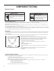
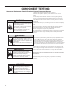
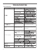
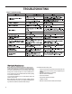
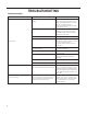
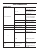
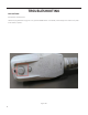
Table Of Contents
- INTRODUCTION
- Important Safety Information
- Personal Injury Or Death Hazards
- Operation of Equipment in During Construction
- Model Number Reference Guide
- Serial Number Reference Guide
- Product Features
- General Specifications 7-9k Electric Heat
- General Specifications 7-9k Heat Pump Models
- General Specifications 12-15k Electric Heat
- General Specifications 12-15k Heat Pump
- Electrical Data
- Function and Control
- Refrigeration Sequence Of Operation
- Refrigerant System Diagram
- PTAC Installation Recommendations
- Wall Sleeve Installation Instructions (PDXWS)
- Alternate Wall Installations
- PXDR10 Drain Kit Installation
- External Drain
- PXGA Standard Grille
- Chassis Install Preparation
- Chassis Installation
- How To Connect
- Install WRT2 Wireless Programmable Thermostat
- Final Inspection & Start-up Checklist
- Refrigerant Charging
- Undercharged Refrigerant Systems
- Overcharged Refrigerant Systems
- Restricted Refrigerant System
- Sealed System Method of Charging/ Repairs
- Hermetic Components Check
- Reversing Valve Description And Operation
- Testing The Reversing Valve Solenoid Coil
- Checking The Reversing Valve
- Touch Test Chart : To Service Reversing Valves
- Compressor Checks
- Compressor Replacement -Special Procedure in Case of Compressor Burnout
- Basic Troubleshooting
- Malfunction Analysis
- Unit Lost Power
- Control Panel Does Not Work
- Malfunction of Temperature Sensor
- E4 Function Error
- E8 Function Error
- E9 Function Error
- Electric Heater Not Running
- Electric Heater Not Running
- 7K Cool+ Electric Heat 230 V
- 9K Cool+ Electric Heat 230v and 265v
- 12K Cool+ Electric Heat 230v and 265v
- 15K Cool+ Electric Heat 230v
- 7K Cool+ Heat Pump 230v
- 9K Cool+ Heat Pump 230v and 265v
- 12K Cool+ Heat Pump 230v and 265v
- 15K Cool+ Heat Pump 230v
- PZE07K3SB,PZE09K3SB, PZE09R3SB, PZE12K3SB, PZE12R3SB, PZE15K3SB
- PZH07K3SB, PZH09K3SB, PZH09R3SB, PZH12K3SB, PZH12R3SB, PZH15K5SB
- Reference Sheet of Celsius and Fahrenheit
- Resistance Table of THERMISTORS (5K)

62 PB
WARNING
ELECTRIC SHOCK HAZARD
Turn off electric power before service or
installation. Extreme care must be used, if it
becomes necessary to work on equipment with
power applied.
Failure to do so could result in serious injury or
death.
Single Phase Resistance Test
Remove the leads from the compressor terminals and set the ohmmeter on the lowest scale (R x 1).
Touch the leads of the ohmmeter from terminals common to start (“C” to “S”). Next, touch the leads of the ohmmeter from
terminals common to run (“C” to “R”).
Add values “C” to “S” and “C” to “R” together and check resistance from start to run terminals (“S” to “R”). Resistance “S” to
“R” should equal the total of “C” to “S” and “C” to “R.”
In a single phase PSC compressor motor, the highest value will be from the start to the run connections (“S” to “R”). The next
highest resistance is from the start to the common connections (“S” to “C”). The lowest resistance is from the run to common.
(“C” to “R”) Before replacing a compressor, check to be sure it is defective.
GROUND TEST
Use an ohmmeter set on its highest scale. Touch one lead to the compressor body (clean point of contact as a good connection
is a must) and the other probe in turn to each compressor terminal. If a reading is obtained the compressor is grounded and
must be replaced.
Check the complete electrical system to the compressor and compressor internal electrical system, check to be certain that
compressor is not out on internal overload.
Complete evaluation of the system must be made whenever you suspect the
compressor is defective. If the compressor has been operating for sometime, a
careful examination must be made to determine why the compressor failed.
Many compressor failures are caused by the following conditions:
1.Improper air ow over the evaporator.
2.Overcharged refrigerant system causing liquid to be returned to the
compressor.
3.Restricted refrigerant system.
4.Lack of lubrication.
5.Liquid refrigerant returning to compressor causing oil to be washed out of
bearings.
6.Noncondensables such as air and moisture in the system. Moisture is
extremely destructive to a refrigerant system.
7.Capacitor.
CHECKING COMPRESSOR EFFICIENCY
The reason for compressor inefciency is normally due to broken or damaged suction and/or discharge valves, reducing the
ability of the compressor to pump refrigerant gas.
This condition can be checked as follows:
1. Install a piercing valve on the suction and discharge or liquid process tube.
2. Attach gauges to the high and low sides of the system.-
3. Start the system to operate the compressor and run a “cooling or heating perfor mance test.” If test shows:
A. Below normal high side pressure
B. Above normal low side pressure
C. Low temperature difference across coil
The compressor valves are faulty - replace the compressor.
WARNING
HIGH PRESSURE HAZARD
Sealed Refrigeration System contains refrigerant
and oil under high pressure.
Proper safety procedures must be followed,
and proper protective clothing must be worn
when working with refrigerants.
Failure to follow these procedures could
result in serious injury or death.
Figure 705 (Resistance Chart)
COMPONENT TESTING
Compressor Checks