
Installation and Operation Manual (2019, 2020, 2021)

WRT2
Wireless Programmable Thermostat
The Friedrich WRT2 is a programmable,
wireless electronic thermostat, which can
be used with the following heating/cooling
applications:
• Single Stage Heat - Cool PTAC Units
• Singe Stage Heat Pump PTAC Units
with or without Electric Heat
Installation and Operation Guide
• Input Voltage: 19 to 30 VAC
• Output Rating: Max. 1.5A per output wire (3A total)
• Temperature Control: 60°F to 90°F (16°C to 32°C)
Specications
• This thermostat is for LOW voltage applications only.
• Turn OFF electricity to all heating and cooling components.
• All wiring must conform to applicable local and national building and electrical codes and
ordinances.
Safety Information
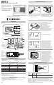
• The WRT2 thermostat comes in two parts: a receiver unit that is wired to the PTAC unit and a
transmitter unit that is installed on the wall and wirelessly communicates with the receiver unit.
Installing the Thermostat
Parts Diagram
Mount Receiver Unit
Pair Transmitter and Receiver Unit
SETTINGS
SETTINGS
Thermostat
Reciever
Thermostat
Transmitter
<30’
PTAC
• Remove the cover from the front of the PTAC
unit.
• Mount the receiver unit using the double-sided
tape provided in the location above.
• Using the WIRING DIAGRAMS section, wire
each output wire into the PTAC terminal
block. Ensure that the bare end is fully seated
into the connector then tighten securely. Pull
gently on wires to ensure they are secure.
• Turn on power to PTAC unit.
• Useaatheadscrewdrivertoseparatethe
front and back housing of the transmitter.
• Take transmitter close to the
expected install location.
• Within 10 minutes of returning power
to the PTAC unit, insert 2xAA brand
name alkaline batteries (included)
into the thermostat transmitter.
• Important: Alkaline batteries must be replaced
once every 2 years regardless of battery
level. Failure to replace batteries can lead to
battery acid leakage and product failure.
• When display says 'YES' press MODE.
• If only 1 receiver has been powered up
within 60 feet of the thermostat transmitter
within the last 10 minutes, then when
this page is displayed press MODE.
• If multiple receivers have been powered
up nearby recently or if you do not see
the screen on the left, please see the
RF PAIRING section for more details.
• Ensure that heat and cool operates correctly.
Onceyouhaveconrmedoperation,cutor
tape-oanyunusedoutputwirescomingfrom
the receiver and replace the PTAC cover.
Installer Button Codes
• Thermostat transmitter
• Thermostat receiver
• Dry wall anchors and mounting screws
• 2 AA batteries
Included in Package
Function Thermostat Mode Key combination / method
Installer menu OFF mode UP + FAN for 5s
Set time and program (installer
menu 13 must be set to ON)
OFF mode UP + MODE for 5s
Toggle Keypad lock/unlock HEAT / COOL mode UP + FAN for 5s
Toggle EMER HEAT HEAT mode DOWN + MODE for 5s
Start RF pairing OFF mode DOWN + FAN for 10s
Output wires
RF pairing
button
Status indicator
Blue = RF
Red = Outputs
Receiver ID label
F
C
AM
PM
SET
MORN
DAY
EVEN
NIGHT
SAT
SUN
MON
TUE
WED
THU
FRI
SCHED UNTIL
YEAR
MONTH
DAYEXIT
RESET
SETTINGS
COOL
HEAT
OFF AUTO
WAIT
FAN
AUTO
LOW
HIGH
2
E
Opening notch
(underneath)
FAN Button
MODE
Button
Down Button
Up
Button
F
C
AM
PM
SET
MORN
DAY
EVEN
NIGHT
SAT
SUN
MON
TUE
WED
THU
FRI
SCHED UNTIL
YEAR
MONTH
DAYEXIT
RESET
SETTINGS
COOL
HEAT
OFF AUTO
WAIT
FAN
AUTO
LOW
HIGH
2
E
Lock
Status
Time
of Day
Period
of Day
Week Day
RF
Status
Air Temp
Half degree for CelsiusCurrent time (programmable mode only)
Thermostat mode
Heating/cooling
indicator
Electric Recovery
indicator (HP only)
Minimumo
time indicator
Fan status indicator
Fan speed indicator
Date setting
Low battery
indicator
Set temp
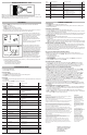
Mount Transmitter Unit
• Mount the thermostat transmitter on an
insidewallaboutvefeetabovetheoor
in an area that has good circulation but is
notdirectlyaectedbyaventorduct.
• Pair the transmitter and receiver, and check
RF connection in desired location prior
to mounting the transmitter on wall.
• Mark the placement of the new mounting
holes through the thermostat base. Using a
3/16" drill bit, drill the holes you have marked
and insert the supplied wall anchors.
• Use supplied screws to mount base to the wall.
• Return the thermostat front cabinet
toitsbasebyhookingthetoprst
and then gently swinging the bottom
of the thermostat into place.
53630
Transmitter
Receiver
Note 1: Make the following Installer Settings for Heat Pump units
System
Type
Changeover
valve type
Required action
Heat Pump B 1. Set Installer Settings Menu #06 to HP
O 1. Set Installer Settings Menu #06 to HP
2. Set Installer Settings Menu #07 to O
Note 2:WhenconguredforHeatPumpoperation,the“Y”wirewillbeenergizedforduringboth
coolingandrst-stageheatingoperation.Donotconnectthe“W1”wiretoanyterminal.
Note 3:The“W2”wireisusedtocallforElectric/Auxiliaryheat.IfyourHeatPumpPTACdoesnot
haveElectricheat,thenthe“W2”wireshouldnotbeusedandInstallerSettingsmenu10(Aux.Stage
Oset)shouldbesetto“OFF”.
Note 4:ForPTACunitswithonlyonefanspeed(single“G”fanterminal),usethe“GL”wireforwiring
andInstallerSettingsmenu12(HighFan)mustbesetto“OFF”.
WIRING DIAGRAM: Heat Pump
W
Y
B
GH
GL
C
R
R
W2
R
Y
O/B
GH
GL
C