Installation and Operation Manual PTAC Packaged Terminal Air Conditioners & Heat Pumps ZoneAire ®
Table of Contents Congratulations····················································································································································· 3 General Instructions··············································································································································· 3 General Specifications···········································································································································
Congratulations Thank you for your decision to purchase Friedrich. Your new Friedrich has been carefully engineered and manufactured to give you many years of dependable, efficient operation, maintaining a comfortable temperature and humidity level. Many extra features have been built into your unit to assure quiet operation, the greatest circulation of cool, dry air, and the most economic operation.
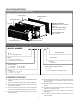
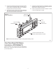
GeneralSpecifications Typical Unit Components and Dimensions WALL SLEEVE OUTDOOR GRILLE DISCHARGE GRILLE PDXWS Wall Sleeve Dimensions: 16" H x 42" W x 13-¾" D Front Cover Dimensions: 16" H x 42" W x 7-¾" D FILTERS Cut-Out Dimensions: 16-¼" x 42-¼" CHASSIS RETURN AIR GRILLE FRONT COVER MODEL NUMBER 3 B Engineering Digit Series PZ = Friedrich Digital PTAC Design Series System E = Cooling with electric heat H = Heat Pump with Auxiliary Heat Chassis S = Standard Nominal Capacity 07 = 7,000 Btuh 0
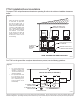
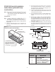
PTACInstallationRecommendations For proper PTAC unit performance and maximum operating life refer to the minimum installation clearances below: Figure 1 PTAC units should be installed no closer than 12" apart when two units are side by side. If three or more PTAC units are to operate next to one another allow a minimum of 36" between units Also, a vertical clearance of 60" should be maintained between units installed.
Wall Sleeve Installation Instructions (PDXWSA) NOTE: Insure that the unit is only installed in a wall structurally adequate to support the unit including the sleeve, chassis and accessories If the sleeve projects more than 8" into the room, a subbase or other means of support MUST be used. Please read these instructions completely before attempting installation. WARNING NOTICE Falling Object Hazard DO NOT allow any pitch toward the inside.
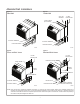
Alternate Wall Instalations Figure 6 Figure 4 CurtainWall Panel Wall WALL OR WINDOW 1/4" MIN PROJECTION CASE FLANGE (BY OTHERS) OPTIONAL SUBBASE OPTIONAL SUBBASE LEVELING SCREW LEVELING SCREW FRP006 FRP004 Figure 5 Figure 7 Frame and Brick Veneer Block and Brick Veneer 1/4" MIN PROJECTION 1/4" MIN PROJECTION CONCRETE LINTEL WOOD FRAME STEEL LINTEL STEEL LINTEL 13-3/4" MIN. WITHOUT SUBBASE 11" MIN.
Figure 8 Wall Sleeve Attachment ALTERNATE FASTENING METHODS (Field Supplied) WALL SLEEVE NOTE: The Wall Sleeve must be horizontally level (side-to-side) and pitched 1/4 bubble to the outside when installed in an WOOD SCREW opening. TOGGLE BOLT The mounting hole location should be approximately 2-4” EXPANSION from the top and bottom of the ANCHOR BOLT sleeve. MOUNTING HOLES PLASTIC ANCHORS FRP008 SCREWS Figure 9 Dimensions A ¼" MIN.
5. Drill two 3/16" holes through each side of the sleeve approximately 4" from top and 4" from bottom of sleeve. Screw four #10 x 1" screws (included) or appropriate fasteners for your installation, through the holes in the sides of the wall sleeve. 6. Apply sealant around the wall sleeve where it projects through the inside and outside wall surfaces. Apply the sealant to the screw heads or the tops of the fasteners used in Step #5. Figure 10 7.
PXDR10DrainKit Installation Instructions (optional for new construction) NOTE:. Determine whether drain will be located within the wall, on the indoor side, or will drain to the exterior of the building. Follow appropriate instructions below depending on your particular type of installation. Internal Drain NOTE:. If installing an internal drain, you MUST install a drain kit on the wall sleeve before the wall sleeve is installed. 1.
External Drain (for new construction or unit replacement) Cover Plate Installation When using an external drain system, the condensate is removed through either of two drain holes on the back of the wall sleeve. Select the drain hole which best meets your drainage situation and install the drain kit. Seal off the other with a cover plate. 4. Mount the foam gasket to the cover plate. Using two #10 x ½" sheet metal screws (provided), attach the cover plate to the remaining drain hole.
PXGAStandard Grille Installation Instructions 5. Insert the remaining screws into the remaining holes and tighten securely. WARNING 1. Remove the center support and weatherboard if still installed in the sleeve. 2. Insert six plastic grommets into the grille openings from the outside of the grille as shown in Figure 13. Falling Object Hazard 3. Insert two #8 x ⅜" sheet metal screws (provided) in the top two outside edge plastic grommets, and tighten them half way into the grommets.
A. Electrical Rating Tables All units are equipped with standard power cords. NOTE: Use Copper Conductors ONLY.Wire sizes are per NEC,check local codes for overseas applications. Table 1 FUSE/CIRCUIT BREAKER Use ONLY type and size fuse or HACR circuit breaker indicated on unit’s rating plate. Proper current protection to the unit is the responsibility of the owner. NOTE: A time delay fuse is provided with 265V units.
TABLE 2 MODEL HEATER kW Power Cord Kit Voltage Amperage Receptacle PZE / PZH07K 3.6 STD 230/208 20 NEMA 6-20r PZE / PZH09K 3.6 STD 230/208 20 NEMA 6-20r PZE / PZH12K 3.6 STD 230/208 20 NEMA 6-20r PZE / PZH15K 5.0 STD 230/208 30 NEMA 6-30r PZE / PZH09R 3.6 STD 265 20 NEMA 7-20r PZE / PZH12R 3.6 STD 265 20 NEMA 7-20r Electrical Wiring for 265 Volt Models To install the line voltage power leads and conduit to chassis, follow the instructions below.
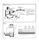
Figure 16 Figure 15 TO CHASSIS JUNCTION STRAIGHT CONNECTOR WALL CONNECTION 4.0 IN. JUNCTION BOX GROUND SCREW GROUND WIRE HARNESS EXPOSE WIRES (1.0 IN.) 18.0 IN. TRIM HARNESS TO LENGTH SPACER STRIP WIRE ENDS (0.5 IN.) TO WALL JUNCTION 5. SPACER Route the cut ends of harness through the conduit connector assembly and flex conduit sleeve. Be sure to use the supplied conduit bushing to prevent damage to the cord by the conduit.
Chassis Install Preparation Check to be sure the wall sleeve, extension (if used), grille, and drain kit are installed properly before chassis installation. 1. Remove the weatherboard and center support from the sleeve (if still in place). Be sure an outdoor grille is attached. NOTE: Figure 18 To avoid breaking the door or hinge pins, do not apply excessive force when installing.
4. CAUTION Remove shipping screw from the vent door, if present. See Fig 21. Figure 21 Unit Damage Hazard Shipping Screw Location Failure to follow this caution may result in equipment damage or improper operation. Failure to remove shipping tape and screw will prevent fresh air vent door from opening and may result in damage to vent door cable. 3. Carefully remove shipping tape from the front panel and vent door.
Chassis Installation 1. Lift unit level and slide unit into wall sleeve until seal rests firmly against front of wall sleeve. 3. Place tabs over top rail (1). Push inward at bottom until panel snaps into place (2). 4. Reinstall front panel.See Figure 24. CAUTION Figure 23 SecuringUnit Excessive Weight Hazard Use two or more people when installing your air conditioner. Failure to do so can result in back or other injury. NOTICE Copper refrigerant tubes are NOT handles.
Product Features The new Friedrich digital PTAC has state of the art features to improve guest comfort,indoor air quality and conserve energy.Through the use of specifically designed control software for the PTAC industry Friedrich has accomplished what other.Manufacturer’s have only attempted –a quiet,dependable,affordable and easy to use PTAC. Below is a list of standard features on every Friedrich PTAC and their benifit to the owner.
DIGITAL DEFROST THERMOSTAT The PZ-Series uses a digital thermostat to accurately monitor the outdoor coil conditions to allow the heat pump to run whenever conditions are correct. Running the PTAC in heat pump mode saves energy and reduces operating costs. The digital thermostat allows maximization of heat pump run time.
System Configuration Figure 25 Air Vent Control Location Fresh Air Vent Control The vent control lever is located on the left side of the unit,behind the front panel. NOTE: The vent door shipping hardware must be removed before using the vent control lever.See page17,Figure21,(Remove Shipping Screw from Vent Door if present). When vent door is set to CLOSE,only the air inside the room is circulated and filtered.See Figure 25. When vent door is set to OPEN,some outdoor air will be drawn into room.
Digital Control User Input Configuration The adjustable control dip switches are located at the front portion of the digital Smart Center. The inputs are only visible and accessible with the front cover removed from the PTAC. Dip Switch Setting 5. 1. Switch 1-Reserved. 2. Switch 2-Heat pump enable/disable. Moving Dip Switch #2 to “OFF” can be set as Emergency Heat Override.
Digital Control Operation Figure 29 Digital Control Panel FRP029 °F vs °C Display Heat/CoolModels (PZE) After pressing the “Heat” button, adjust the set point and the unit will cycle the electric strip on and off to maintain a comfortable room. The heater will come on anytime that the room temperature is 2 °F below the set point. The fan will either continuous or cycling, depends on the “Constant Fan” selection. See Constant Fan section.
Remote Control Thermostat Installation To control the unit with a wall mounted thermostat follow the steps below: Install Thermostat 1. Approximately 5 ft from the floor. 2. Close to or in a frequently used room,preferably on an inside wall. 3. On a section of wall without pipes or ductwork. The Thermostat should NOT be mounted: 1. Unplug the unit before doing any work 2. Remove the low voltage terminal block from the unit. 3.
Front Desk Control Terminal WARNING The Friedrich PZ model PTAC has built-in provisions for connection to an external switch to control power to the unit. The switch can be a central desk control system. For front desk control operation, connect one side of the normal open switch to the R terminal and the other to the FD terminal. The control logic as below: (a). Turn ON unit: short R and FD then release for one time within 5s. (b). Turn OFF unit: short R and FD then release for twice within 5s. (c).
Final Inspection & Start-up Checklist Inspect and ensure that all components and accessories have been installed properly and that they have not been damaged during the installation process. Check the condensate water drain(s) to ensure they are adequate for the removal of condensate water, and that they meet the approval of the end user. Ensure that all installations concerning clearances around the unit have been adhered to.
Basic Troubleshooting Malfunction Possible Reasons S olution power line bad, units don’t have power supply. Check the indicator LED on the LCID power head, it should be lit up, if not, push the RESET button, if still don’t have voltage, but power grid has output, you need to change the power cord. Power cord protection trip. Check the power cord if somewhere is broken, push the RESET button. If not solved, replace the power cord. Power cord isn’t fixed well.
Malfunction Outlet temperature is not always cooling/heating Possible Reasons Solution When outdoor ambient temp is low, the heat Outlet temperature is not high enough when pump will not be able to offer enough heat. Soon heating by heat pump. after that, the E-heater will come on to heat. Fan stops when cooling/heating. It is normal when the CONSTANT FAN is OFF. Youcan enable the CONSTANT FAN. Outdoor is dripping water Not install the drain pipe kit. Install the drain pipe kit.
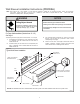
Accessories New Construction Accessories PDXWSA WALL SLEEVE Galvanized zinc coated steel is prepared in an 11step process, then powder coated with a polyester finish and cured in an oven for exceptional durability. The wall sleeve is insulated for sound absorption and thermal efficiency, 16" H x 42" W x 13 3 /4" D. PDXWSA PDXWSEXT18 DEEP WALL SLEEVE For walls up to 17 1/2" D. PDXWSEXT24 DEEP WALL SLEEVE For walls up to 23 1/2" D.
New Construction Accessories PDXDAA LATERAL DUCT ADAPTER Attaches to the Friedrich PTAC/PTHP unit to direct up to 35% of the total airflow to a second room. The unit-mounted duct plenum features a front-mounted aluminum grille that has two positions to provide the most optimal air direction. The air may be directed to either the left or the right of the unit through the supplied 3 1/2 H" x 7 W" x 47" L plenum. Plenum may be cut to length by the installer.
Friedrich Air Conditioning Co. 10001 Reunion Place, San Antonio, TX 78216 800.541.6645 www.friedrich.com PZ-SERIES PACKAGED TERMINAL AIR CONDITIONERS LIMITED WARRANTY SAVE THIS CERTIFICATE.It gives you specific rights.You may also have other rights which may vary from state to state and province to province. In the event that your unit needs servicing, contact your nearest authorized service center.