
Installation & Operation Manual (ZoneAire Series 2016 - 2020) (2016, 2017, 2018, 2019, 2020)
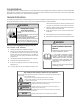
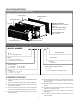
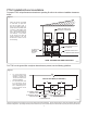
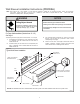
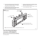
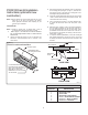
Table Of Contents
- Table of Contents
- Congratulations
- General Instructions
- WARNING
- Refrigeration system under high pressure
- WARNING
- Read Installation Operation Manual
- Your safety and the safety of others are very impo
- General Specifications
- Typical Unit Components and Dimensions
- Installation Checklist
- PTAC Installation Recommendations
- For proper PTAC unit performance and maximum opera
- For PTACs on the ground floor or anytime obstructi
- Wall Sleeve Installation Instructions (PDXWSA)
- WARNING
- Falling Object Hazard
- Alternate Wall Instalations
- One-Piece Deep Wall Sleeve Installation (PDXWSEXT
- PXDR10 Drain Kit Installation Instructions (option
- Internal Drain
- FRONT VIEW
- Drain Tube Installation (See Figure 12)
- Cover Plate Installation
- DETAIL B
- PXGA Standard Grille Insta lation Instructions
- WARNING
- Falling Object Hazard
- Electrical Rating Tables
- All units are equipped with standard power cords.
- Electrical Shock Hazard
- Power Cord Information (230/208V models only)
- Electrical Wiring for 265 Volt Models
- Power Cord Installation
- To install the line voltage power leads and condu
- Electrical Shock Hazard
- Chassis Install Preparation
- Check to be sure the wall sleeve, extension (if us
- Suffocation Hazards
- CAUTION
- Unit Damage Hazard
- Chassis Installation
- Excessive Weight Hazard
- System Configuration
- Fresh Air Vent Control
- Adjusting Air
- Backside of Front Panel
- Adjusting Louvers
- Digital Control User Input Configuration
- Dip Switch Setting
- Dip Switches
- Digital Control Operation
- Digital Control Panel
- °F vs °C Display
- Cooling Mode
- Heating Mode
- Heat Pump Models (PZH)
- Heat/Cool Models (PZE)
- Emergency Heat Operation
- Constand Fan
- Setting Temperature Limit
- Remote Control Thermostat Installation
- Install Thermostat
- The Thermostat should NOT be mounted:
- To control the unit with a wall mounted thermosta
- Thermostat Connections
- Control board with optional PDXRTB escutcheon kit
- Front Desk Control Terminal
- Energy Management
- Final Inspection & Start-up Checklist
- WARNING
- Decorative Front
- Fan Motor & Compressor
- Wall Sleeve
- Basic Troubleshooting
- Accessories
- PZ-SERIES

10
PXDR10DrainKit Installation
Instructions(optional fornew
construction)
NOTE:. Determine whether drain will be located within the wall, on the
indoor side, or will drain to the exterior of the building.
Follow appropriate instructions below depending on your
particular type of installation.
InternalDrain
NOTE:. If installing an internal drain, you MUST install a drain kit
on the wall sleeve before the wall sleeve is installed.
1. Refer to Figure 11 and locate the drain within the “Preferred”
area of best drainage. Maintain at least a ½” clearance from the
embossed area.
2. Using the mounting plate with the ½” hole as a template, mark
and drill two, 3/16” mounting holes and a ½” drain hole in the
sleeve bottom .
Figure 11
Drain Kit Location and Installation
OPTIONAL AREA
PREFERRED AREA-
NO FOAM INSULATION
3. Remove the backing from the gasket and mount it on the flat side
of the mounting plate. (See Figure 12, Page 11). Insert the drain
tube through the hole in the gasket and mounting plate so the
tube flange will be against the wall sleeve.
4. Position the assembly beneath the drilled holes and secure it with #
10-24x ½" machine screws and lock nuts provided . Seal the tops
of the screws with silicone caulking.
5. Use ½" ID copper tube, PVC pipe, or vinyl hose (obtained locally)
to connect the internal drain tube to the drain system in the
building.
6. Referring to Figure 12,Detail A, Page 11,locate and assemble the
two cover plates and gaskets over the drain holes at the rear of
the wall sleeve.Attach them with the #10 sheet metal screws
provided.Make certain that the four overflow slots at the rear of
the wall sleeve are not blocked (See drawing of the back of the
sleeve Figure 12, Page 11).
7. If a deep wall extension (PDXWSEXT) is used, after installing the
field supplied flashing,caulk as required. Be sure to caulk around
the flashing and the wall sleeve where the hole was drilled for the
drain tube.
SCREW
WALL SLEEVE
GASKET
MOUNTING
PLATE
DRAIN TUBE
NUT
SIDE VIEW
IF THE DRAIN MUST BE
LOCATED IN THE OPTIONAL
AREA, THE FOAM INSULATION
MUST BE CUT AWAY AND
REMOVED TO ALLOW ACCESS
3"
TO THE DRAIN.
FRONT VIEW
FRP011
PXDR10
QUANTITY
DESCRIPTION
2
COVER PLATES
1
MOUNTING PLATE
1
DRAIN TUBE
3
MOUNTING PLATE GASKET
4
#10 X ½” SHEET METAL SCREWS
2
#10-24 X ½ ” MACH. SCREWS
2
#10-24 X ½" LOCKNUTS