
Installation & Operation Manual (ZoneAire Series 2016 - 2020) (2016, 2017, 2018, 2019, 2020)
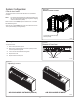
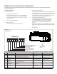
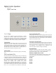
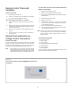
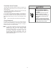
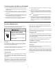
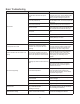
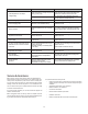
Table Of Contents
- Table of Contents
- Congratulations
- General Instructions
- WARNING
- Refrigeration system under high pressure
- WARNING
- Read Installation Operation Manual
- Your safety and the safety of others are very impo
- General Specifications
- Typical Unit Components and Dimensions
- Installation Checklist
- PTAC Installation Recommendations
- For proper PTAC unit performance and maximum opera
- For PTACs on the ground floor or anytime obstructi
- Wall Sleeve Installation Instructions (PDXWSA)
- WARNING
- Falling Object Hazard
- Alternate Wall Instalations
- One-Piece Deep Wall Sleeve Installation (PDXWSEXT
- PXDR10 Drain Kit Installation Instructions (option
- Internal Drain
- FRONT VIEW
- Drain Tube Installation (See Figure 12)
- Cover Plate Installation
- DETAIL B
- PXGA Standard Grille Insta lation Instructions
- WARNING
- Falling Object Hazard
- Electrical Rating Tables
- All units are equipped with standard power cords.
- Electrical Shock Hazard
- Power Cord Information (230/208V models only)
- Electrical Wiring for 265 Volt Models
- Power Cord Installation
- To install the line voltage power leads and condu
- Electrical Shock Hazard
- Chassis Install Preparation
- Check to be sure the wall sleeve, extension (if us
- Suffocation Hazards
- CAUTION
- Unit Damage Hazard
- Chassis Installation
- Excessive Weight Hazard
- System Configuration
- Fresh Air Vent Control
- Adjusting Air
- Backside of Front Panel
- Adjusting Louvers
- Digital Control User Input Configuration
- Dip Switch Setting
- Dip Switches
- Digital Control Operation
- Digital Control Panel
- °F vs °C Display
- Cooling Mode
- Heating Mode
- Heat Pump Models (PZH)
- Heat/Cool Models (PZE)
- Emergency Heat Operation
- Constand Fan
- Setting Temperature Limit
- Remote Control Thermostat Installation
- Install Thermostat
- The Thermostat should NOT be mounted:
- To control the unit with a wall mounted thermosta
- Thermostat Connections
- Control board with optional PDXRTB escutcheon kit
- Front Desk Control Terminal
- Energy Management
- Final Inspection & Start-up Checklist
- WARNING
- Decorative Front
- Fan Motor & Compressor
- Wall Sleeve
- Basic Troubleshooting
- Accessories
- PZ-SERIES

23
Digital Control Operation
Figure 29
Digital Control Panel
FRP029
°F vs °C Display
The unit is factory configured to display all temperatures in degrees
Fahrenheit (°F). To switch to degrees Celsius, press the “UP” and
“DOWN” buttons simultaneously for three seconds. The display will switch
to C degrees. To revert back to °F, press the “UP” and “DOWN” buttons
simultaneously for three seconds. The display will switch to F degrees.
CoolingMode
Pressing the “Cool” button after turn the unit on will put the unit into
cooling mode. Press “UP” or “DOWN” button to adjust the set point, the
unit will cycle the compressor on and off to maintain a comfortable room.
The compressor will cycle on anytime that the room temperature is 2 °F
above the set point. The fan will either continuous or cycling, depends on
the “Constant Fan” selection. See Constant Fan section.
Heating Mode
After turn on the unit, press the “Heat” button will put the unit into heating
mode.
Heat Pump Models (PZH)
When the “Heat” button is pressed initially the unit may call for heat pump
or electric strips (depends on different ambient temperature or DIP Switch
4 settings) to bring the room to the set point. When the room temperature
falls 2 °Fbelow the set point, the unit will cycle the compressor or electric
strip on. The fan will either continuous or cycling, depends on the
“Constant Fan” selection. See Constant Fan section.
When the outdoor coil temperature falls below 26 °F for 3 minutes, the
unit will operate the electric strip instead of heat pump. Only when the
room temperature reaches the set point and the outdoor coil temperature
rises to 41 °F, the compressor will be allowed to operate again.
Heat/CoolModels (PZE)
After pressing the “Heat” button, adjust the set point and the unit will cycle
the electric strip on and off to maintain a comfortable room. The heater will
come on anytime that the room temperature is 2 °F below the set point.
The fan will either continuous or cycling, depends on the “Constant Fan”
selection. See Constant Fan section.
Emergency Heat Operation
In the event of a compressor failure in heat pump mode, the compressor
may be locked out to provide heat through the electric strip heater. This
feature ensures that even in the unlikely event of a compressor failure, the
room temperature can be maintained until the compressor can be
serviced. Dip switch 2 controls the emergency heat setting.
Constant Fan
Pressing the “Constant Fan” button will provide constant or cycle fan
operation in cooling or heating modes. The fan speed selection is made
by pressing either “High” or “Low” or “Auto” fan speed button.
Setting Temperature Limit
Hold "UP" and "High" fan speed buttons at the same time for 5s, digital
tube displayer will show R1-R8, default is R8. The temperature(°F)
range as below:
R1: 63-86
R2: 65-86
R3: 72-90
R4: 72-74
R5: 67-92
R6: 69-90
R7: 68-72
R8: 60-90