Service/ Parts Manual PTAC ZONEAIRE® SELECT Standard Chassis Models PZE07K3SB PZH07K3SB 7K 9K PZE09K3SB, PZE09R3SB PZH09K3SB, PZH09R3SB 12K PZE12K3SB, PZE12R3SB PZH12K3SB, PZH12R3SB 15K PZE15K5SB PZH15K5SB 1 94151400_07
Table of Contents 2 TABLE OF CONTENTS INTRODUCTION Important Safety Information Personal Injury Or Death Hazards Operation of Equipment in During Construction Model Number Reference Guide Serial Number Reference Guide Product Features SPECIFICATIONS General Specifications 7-9k Electric Heat General Specifications 7-9k Heat Pump Models General Specifications 12-15k Electric Heat General Specifications 12-15k Heat Pump Electrical Data OPERATION Function and Control Refrigeration Sequence Of Ope
TABLE OF CONTENTS 12K Cool+ Electric Heat 230v and 265v 15K Cool+ Electric Heat 230v 7K Cool+ Heat Pump 230v 9K Cool+ Heat Pump 230v and 265v 12K Cool+ Heat Pump 230v and 265v 15K Cool+ Heat Pump 230v PARTS CATALOG PZE07K3SB,PZE09K3SB, PZE09R3SB, PZE12K3SB, PZE12R3SB, PZE15K3SB PZH07K3SB, PZH09K3SB, PZH09R3SB, PZH12K3SB, PZH12R3SB, PZH15K5SB ACCESSORIES APPENDIX Reference Sheet of Celsius and Fahrenheit Resistance Table of THERMISTORS (5K) WARRANTY FRIEDRICH AUTHORIZED PARTS DEPOTS 3 85 86 87
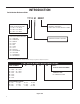
INTRODUCTION Important Safety Information The information in this manual is intended for use by a qualified technician who is familiar with the safety procedures required for installation and repair, and who is equipped with the proper tools and test instruments required to service this product.
Personal Injury Or Death Hazards SAFETY FIRST INTRODUCTION WARNING AVERTISSEMENT ADVERTENCIA Do not remove, disable or bypass this unit’s safety devices. Doing so may cause fire, Doing so may cause fire, injuries, or death. Ne pas supprime, désactiver ou contourner cette l´unité des dispositifs de sécurité, faire vous risqueriez de provoquer le feu, les blessures ou la mort. No eliminar, desactivar o pasar por alto los dispositivos de seguridad de la unidad.
INTRODUCTION Personal Injury Or Death Hazards 6 • REFRIGERATION SYSTEM REPAIR HAZARDS: • Use approved standard refrigerant recovering procedures and equipment to relieve high pressure before opening system for repair. • Do not allow liquid refrigerant to contact skin. Direct contact with liquid refrigerant can result in minor to moderate injury. • Be extremely careful when using an oxy-acetylene torch. Direct contact with the torch’s flame or hot surfaces can cause serious burns.
INTRODUCTION Operation of Equipment in During Construction • OPERATION OF EQUIPMENT MUST BE AVOIDED DURING CONSTRUCTION PHASES WHICH WILL PRODUCE AIRBORNE DUST OR CONTAMINTES NEAR OR AROUND AIR INTAKE OPENINGS: • Wood or metal framing; • Drywalling or sheathing, • Spackling or applying joint compound. • Sanding or grinding. • Moulding or trimwork.
INTRODUCTION This service manual is designed to be used in conjunction with the installation and operation manuals provided with each air conditioning system. This service manual was written to assist the professional service technician to quickly and accurately diagnose and repair malfunctions. Installation procedures are not given in this manual. They are given in the Installation and Operation Manual which can be aquired on the Friedrich website (www.friedrich.com).
Serial Number Reference Guide INTRODUCTION 17 12 M 00001 NUMERIC SEQUENCE FIRST UNIT OF EACH MONTH = 00001 YEAR OF MANUFACTURE 17 = 2017 18 = 2018 19 = 2019 20 = 2020 21 = 2021 22 = 2022 MONTH OF MANUFACTURE 01 = JANUARY 02 = FEBRUARY 03 = MARCH 04 = APRIL 05 = MAY 06 = JUNE 07 = JULY 08 = AUGUST 09 = SEPTEMBER 10 = OCTOBER 11 = NOVEMBER 12 = DECEMBER MANUFACTURING LOCATION Refer to the Chart below for Serial Numbers beginning with an Alpha Sequence PTAC Serial Number Identification Guide SERIAL NUMB
Product Features Product Features INTRODUCTION The new Friedrich digital PTAC has state of the art features to improve guest comfort,indoor air quality and conserve energy.Through the use of specifically designed control software for the PTAC industry Friedrich has accomplished what other.Manufacturer’s have only attempted –a quiet,dependable,affordable and easy to use PTAC. Below is a list of standard features on every Friedrich PTAC and their benifit to the owner.
INTRODUCTION Product Features DIGITAL DEFROST THERMOSTAT The PZ-Series uses a digital thermostat to accurately monitor the outdoor coil conditions to allow the heat pump to run whenever conditions are correct. Running the PTAC in heat pump mode saves energy and reduces operating costs. The digital thermostat allows maximization of heat pump run time.
SPECIFICATIONS General Specifications 7-9k Electric Heat PZE Series with Electric Heat PZE07K PZE09K PZE09R Cooling Btu 7200/6800 9600/9400 9200 Cooling Watts 600/565 815/800 800 Energy Efficiency Ratio, EER 12.0 11.8/11.8 11.5 Heater Size (kW) 3.6 3.6 3.6 Moisture Removal (pints/hr.) 0.7 1.2 1.6 Sensible Heat Ratio 0.87 0.82 0.82 Voltage (1 PHASE, 60 Hz) 230/208 230/208 265 Volt Range 253-187 253-187 292-239 Current (Amps) 2.6/2.7 3.5/3.8 4.2 Power factor 0.99 0.
SPECIFICATIONS General Specifications 7-9k Heat Pump Models PTAC Heat Pump models PZH07K PZH09R PZH09R Cooling Btu 7200/6800 9600/9400 9200 Cooling Watts 600/565 815/800 800 Energy Efficient Ratio, Eer 12.0/12.0 11.8/11.8 11.5 Reverse Heating Btu 6400/6300 8500/8200 8500 Heating Watts 530/520 710/685 710 Cop 3.55/3.54 3.51/3.51 3.51 Moisture Removal (Pints/Hr.) 0.7 1.2 1.6 Sensible Heat Ratio 0.87 0.82 0.
SPECIFICATIONS General Specifications 12-15k Electric Heat PTAC Electric Heat models PZH12K PZH12R PZH15K Cooling Btu 12000/11800 12000 14500/14300 Cooling Watts 1050/1035 1130 1420/1400 Energy Efficiency Ratio, EER 11.4/11.4 10.6 10.2/10.2 Heater Size (kW) 3.6 3.6 5.0 Moisture Removal (pints/hr.) 2.1 3.2 3.0 Sensible Heat Ratio 0.77 0.72 0.72 Voltage (1 PHASE, 60 Hz) 230/208 265 230/208 Volt Range 253-187 292-239 253-187 Current (Amps) 4.5/5.0 5.92 6.2/6.
SPECIFICATIONS General Specifications 12-15k Heat Pump PTAC Heat Pump models PZH12K PZH12R PZH15K Cooling Btu 12000/11800 12000 14500/14300 Cooling Watts 1050/1035 1130 1420/1400 Energy Efficient Ratio, Eer 11.4/11.4 10.6 10.2/10.2 Reverse Heating Btu 11000/10800 11400 13600/13200 Heating Watts 930/920 1000 1180/1150 Cop 3.47/3.44 3.34 3.38/3.36 Moisture Removal (Pints/Hr.) 2.1 3.2 3.0 Sensible Heat Ratio 0.77 0.72 0.
SPECIFICATIONS 42 16 21 1/2 10 40 Unit:inch Figure 205 ( Chassis Specs) E Figure 206 (Typical Unit Components and Dimensions) 16
SPECIFICATIONS Electrical Data A. Electrical Rating Tables All units are equipped with standard power cords. NOTE: Use Copper Conductors ONLY.Wire sizes are per NEC,check local codes for overseas applications. Table 1 FUSE/CIRCUIT BREAKER Use ONLY type and size fuse or HACR circuit breaker indicated on unit’s rating plate. Proper current protection to the unit is the responsibility of the owner. NOTE: A time delay fuse is provided with 265V units.
SPECIFICATIONS Electrical Data TABLE 2 MODEL HEATER kW Power Cord Kit Voltage Amperage Receptacle PZE / PZH07K 3.6 STD 230/208 20 NEMA 6-20r PZE / PZH09K 3.6 STD 230/208 20 NEMA 6-20r PZE / PZH12K 3.6 STD 230/208 20 NEMA 6-20r PZE / PZH15K 5.0 STD 230/208 30 NEMA 6-30r PZE / PZH09R 3.6 STD 265 20 NEMA 7-20r PZE / PZH12R 3.
SPECIFICATIONS Electrical Data Figure 16 Figure 15 TO CHASSIS JUNCTION STRAIGHT CONNECTOR WALL CONNECTION 4.0 IN. JUNCTION BOX GROUND SCREW GROUND WIRE HARNESS EXPOSE WIRES (1.0 IN.) 18.0 IN. TRIM HARNESS TO LENGTH FRP016 Figure 17 LEADING SIDE FOR WIRE HARNESS INSERTION SPACER STRIP WIRE ENDS (0.5 IN.) TO WALL JUNCTION SPACER Route the cut ends of harness through the conduit connector assembly and flex conduit sleeve.
OPERATION Function and Control Buttons and Display 1) Buttons There are ON/OFF, UP, DOWN, HEAT, COOL, CONSTANT FAN and fan speed of HIGH, LOW, AUTO buttons. 1. ON/OFF: Press to turn power on or off to the unit. 2. COOL, HEAT: choose the mode of operation 3. HIGH, LOW, AUTO: choose the fan speed. 4. UP, DOWN: Adjust the setting temperature , default: 60-90°F(16~32°F). 2) Dual 8 Digital Tube Displayer and LED Two 8 digital tube and 7 LEDs (ON/OFF, HIGH, LOW, AUTO, HEAT, COOL, CONSTANT FAN) 1.
OPERATION Function and Control 2) Heating Mode Working condition and process for heating: When T1≤Ts -2°F(1°C), the unit is running in heating mode. Heat pump or electric heating will start depending on the ambient temperature condition or the heating priority setting (#4 DIP SWITCH, ON- for heat pump and OFF-for electric heating). When T1≥Ts+ 2°F(1°C), the heating is turned OFF.
OPERATION Function and Control Special Function 1) Advanced Settings Fahrenheit / Centigrade display Fahrenheit and Centigrade display mode can be switched over by holding the UP and DOWN two buttons at the same time for 3s. Setting Temperature Range Hold UP and HIGH fan speed buttons at the same time for 5s, digital tube displayer will show R1—R8, default is R8. The temperature range as the table below: NO.
OPERATION Digital Control User Input Configuration The adjustable control dip switches are located at the front portion of the digital Smart Center. The inputs are only visible and accessible with the front cover removed fromthe PTAC. 5. 1. Switch 1-Reserved. 2. Switch 2-Heat pump enable/disable. Moving Dip Switch #2 to “OFF” can be set as Emergency Heat Override.
OPERATION Digital Control The unit is factory configured to display all temperatures in degrees Fahrenheit (°F). To switch to degrees Celsius, press the “UP” and “DOWN” buttons simultaneously for three seconds. The display will switch to C degrees. To revert back to °F, press the “UP” and “DOWN” buttons simultaneously for three seconds. The display will switch to F degrees. Pressing the “Cool” button after turn the unit on will put the unit into cooling mode.
Refrigeration Sequence Of Operation OPERATION A good understanding of the basic operation of the refrigeration system is essential for the service technician. Without this understanding, accurate troubleshooting of refrigeration system problems will be more difficult and time consuming, if not (in some cases) entirely impossible. The refrigeration system uses four basic principles in its operation which are as follows: 1. “Heat always flows from a warmer body to a cooler body.” 2.
OPERATION Refrigerant System Diagram (1)Cooling + Heat Pump + Auxiliary Electric Heater PZH07K3SB PZH09K3SB PZH09R3SB PZH12K3SB PZH12R3SB PZH15K5SB COOLED AIR CENTRIFUGAL OR CROSS FAN AXIAL FAN HOT AIR HOT DISCHARGED AIR COOLED AIR COMPRESSOR INDOOR COILS OUTDOOR COILS ELECTRIC HEATER CAPILLARY NOTES: REFRIGERANT FLOW DIRECTION COOLING MODE HEATING MODE (2) Cooling + Electric Heater PZE07K3SB PZE09K3SB PZE09R3SB PZE12K3SB PZE12R3SB PZE15K5SB CENTRIFUGAL OR CROSS FAN AXIAL FAN COOLED AIR HO
Coils & Chassis Routine Maintenance NOTE: Do not use a caustic cleaning agent on coils or base pan. Use a biodegradable cleaning agent and degreaser. The use of harsh cleaning materials may lead to deterioration of the aluminum fins or the coil end plates. The indoor coil and outdoor coils and base pan should be inspected periodically (annually or semi-annually) and cleaned of all debris (lint, dirt, leaves, paper, etc.) as necessary. Under extreme conditions, more frequent cleaning may be required.
INSTALLATION PTAC Installation Recommendations PTACInstallationRecommendations For proper PTAC unit performance and maximum operating life refer to the minimum installation clearances below: Figure 1 PTAC units should be installed no closer than 12" apart when two units are side by side. If three or more PTAC units are to operate next to one another allow a minimum of 36" between units Also, a vertical clearance of 60" should be maintained between units installed.
INSTALLATION Wall Sleeve Installation Instructions (PDXWS) Wall Sleeve Installation Instructions (PDXWSA) NOTE: Insure that the unit is only installed in a wall structurally adequate to support the unit including the sleeve, chassis and accessories If the sleeve projects more than 8" into the room, a subbase or other means of support MUST be used. Please read these instructions completely before attempting installation. WARNING NOTICE Falling Object Hazard DO NOT allow any pitch toward the inside.
INSTALLATION Alternate Wall Wall Installations Alternate Instalations Figure 6 Figure 4 CurtainWall Panel Wall WALL OR WINDOW 1/4" MIN PROJECTION CASE FLANGE (BY OTHERS) OPTIONAL SUBBASE OPTIONAL SUBBASE LEVELING SCREW LEVELING SCREW FRP006 FRP004 Figure 5 Figure 7 Frame and Brick Veneer Block and Brick Veneer 1/4" MIN PROJECTION 1/4" MIN PROJECTION CONCRETE LINTEL WOOD FRAME STEEL LINTEL STEEL LINTEL 13-3/4" MIN. WITHOUT SUBBASE 11" MIN.
INSTALLATION Alternate Wall Installations Figure 8 Wall Sleeve Attachment ALTERNATE FASTENING METHODS (Field Supplied) WALL SLEEVE NOTE: The Wall Sleeve must be horizontally level (side-to-side) and pitched 1/4 bubble to the outside when installed in an WOOD SCREW opening. TOGGLE BOLT The mounting hole location should be approximately 2-4” EXPANSION from the top and bottom of the ANCHOR BOLT sleeve. MOUNTING HOLES PLASTIC ANCHORS FRP008 SCREWS Figure 9 Dimensions A ¼" MIN.
INSTALLATION Alternate Wall Installations 5. Drill two 3/16" holes through each side of the sleeve approximately 4" from top and 4" from bottom of sleeve. Screw four #10 x 1" screws (included) or appropriate fasteners for your installation, through the holes in the sides of the wall sleeve. 6. Apply sealant around the wall sleeve where it projects through the inside and outside wall surfaces. Apply the sealant to the screw heads or the tops of the fasteners used in Step #5. Figure 10 7.
INSTALLATION PXDR10 Drain Kit Installation PXDR10DrainKit Installation Instructions (optional for new construction) NOTE:. Determine whether drain will be located within the wall, on the indoor side, or will drain to the exterior of the building. Follow appropriate instructions below depending on your particular type of installation. Internal Drain NOTE:. If installing an internal drain, you MUST install a drain kit on the wall sleeve before the wall sleeve is installed. 1.
External Drain INSTALLATION External Drain (for new construction or unit replacement) Cover Plate Installation When using an external drain system, the condensate is removed through either of two drain holes on the back of the wall sleeve. Select the drain hole which best meets your drainage situation and install the drain kit. Seal off the other with a cover plate. 4. Mount the foam gasket to the cover plate.
PXGA Standard Grille INSTALLATION PXGAStandard Grille Installation Instructions 5. Insert the remaining screws into the remaining holes and tighten securely. WARNING 1. Remove the center support and weatherboard if still installed in the sleeve. 2. Insert six plastic grommets into the grille openings from the outside of the grille as shown in Figure 13. Falling Object Hazard 3.
INSTALLATION Chassis Preparation Chassis InstallInstall Preparation Check to be sure the wall sleeve, extension (if used), grille, and drain kit are installed properly before chassis installation. 1. Remove the weatherboard and center support from the sleeve (if still in place). Be sure an outdoor grille is attached. NOTE: Figure 18 To avoid breaking the door or hinge pins, do not apply excessive force when installing.
INSTALLATION Chassis Install Preparation 4. CAUTION Remove shipping screw from the vent door, if present. See Fig 21. Figure 21 Unit Damage Hazard Shipping Screw Location Failure to follow this caution may result in equipment damage or improper operation. Failure to remove shipping tape and screw will prevent fresh air vent door from opening and may result in damage to vent door cable. 3. Carefully remove shipping tape from the front panel and vent door.
INSTALLATION Chassis Installation Chassis Installation 1. Lift unit level and slide unit into wall sleeve until seal rests firmly against front of wall sleeve. 3. Place tabs over top rail (1). Push inward at bottom until panel snaps into place (2). 4. Reinstall front panel.See Figure 24. CAUTION Figure 23 SecuringUnit Excessive Weight Hazard Use two or more people when installing your air conditioner. Failure to do so can result in back or other injury.
How To Connect Chassis Install INSTALLATION Preparation Check to be sure the wall sleeve, extension (if used), grille, and drain kit are installed properly before chassis installation. 1. Remove the weatherboard and center support from the sleeve (if still in place). Be sure an outdoor grille is attached. NOTE: Figure 18 To avoid breaking the door or hinge pins, do not apply excessive force when installing.
INSTALLATION Install WRT2 Wireless Programmable Thermostat NOTE: Instructions to install the WRT2 thermostat are included in this service manual. For all other thermostat installation and troubleshooting, refer to the Installation/ Operation Manual and the applicable thermostat Accessory manual.
INSTALLATION Install WRT2 Wireless Programmable Thermostat Installing the Thermostat The WRT2 thermostat comes in two parts: a receiver unit that is wired to the PTAC unit and a transmitter unit that is installed on the wall and wirelessly communicates with the receiver unit. Mount Receiver Unit (Figure 503) 1. Remove the cover from the front of the PTAC unit. 2. Mount the receiver unit using double-sided tape. 3.Wire each output wire into the PTAC terminal block.
INSTALLATION Install WRT2 Wireless Programmable Thermostat To control the unit with a wall mounted thermostat follow the steps below: 1. Restore power to the PTAC unit. 2. Under stand-by mode, press the “Cool” and “UP” buttons simultaneously for three seconds, the digital displays character“r”, and the beeper chime twice. 3. The unit is now controlled by the wall thermostat only. 4. If the accessory escutcheon kit (PDXRTB) is to be used, install it over the existing control panel.
INSTALLATION Install WRT2 Wireless Programmable Thermostat Pair Transmitter and Receiver Unit 1. Insert 2xAA brand name alkaline batteries (included) into the thermostat transmitter. NOTE: Important: Alkaline batteries must be replaced once every 2 years regardless of battery level. Failure to replace batteries can lead to battery acid leakage and product failure. 2. Turn on power to PTAC unit. 3. Use a flat head screw driver to separate the front and back housing of the transmitter. (See Figure 509) 4.
INSTALLATION Install WRT2 Wireless Programmable Thermostat RF PAIRING The RF icon in the top right corner of the LCD shows the RF connection state between transmitter and receiver. (Figure 513) • BLANK: No receiver paired • SOLID: Transmitter and receiver connected • FLASHING: Receiver paired but disconnected SETTINGS • When you first power up a transmitter and receiver they will be in pairing mode for 10 minutes.
INSTALLATION Install WRT2 Wireless Programmable Thermostat Mount Transmitter Unit 1. Mount the thermostat transmitter on an inside wall about five feet above the floor in an area that has good circulation but is not directly affected by a supply vent or return. NOTE: .For optimal RF Pairing and performance, the transmiiter should be mounted within 30 feet of the receiver, and have a direct line of sight. 3. Mark the placement of the new mounting holes through the thermostat base.
INSTALLATION Install WRT2 Wireless Programmable Thermostat INSTALLER SETTINGS HOW TO ENTER • Set thermostat to OFF mode • Hold UP + FAN for 5 seconds HOW TO NAVIGATE • Press UP or DOWN to change setting value • Press MODE to save setting value and proceed to next setting option • Press FAN to return to previous setting option HOW TO EXIT • Press MODE until last setting page (99) has been saved or leave thermostat with no button pressfor 60 seconds • Note: You must press MODE to save each setting value 46
INSTALLATION Install WRT2 Wireless Programmable Thermostat NORMAL OPERATION CHANGING MODE • Press MODE button to initiate mode selection menu • Press MODE button until desired system mode is blinking. After 2 seconds of no button press desired mode is selected CHANGING SET TEMPERATURE • Ensure thermostat is in correct system mode (Heat, Cool or Auto) • Press UP or DOWN button. New set temperature will be displayed in large digits.
INSTALLATION Final Inspection & Start-up Checklist Final Inspection & Start-up Checklist q Inspect and ensure that all components and accessories have been installed properly and that they have not been damaged during the installation process. q Check the condensate water drain(s) to ensure they are adequate for the removal of condensate water, and that they meet the approval of the end user. q Ensure that all installations concerning clearances around the unit have been adhered to.
R-410A SEALED SYSTEM REPAIR WARNING Refrigeration system under high pressure O service this equipment. R410A systems operate at higher pressures than R22 equipment. Appropriate safe service and handling practicces must be used. Only use gauge sets designed for use with R410A. Do not use standard R22 gauge sets. The following is a list of important considerations when working with R-410A equipment 1. R-410A pressure is approximately 60% higher than R-22 pressure. 2.
R-410A SEALED SYSTEM REPAIRS WARNING RISK OF ELECTRIC SHOCK Unplug and/or disconnect all electrical power to the unit before performing inspections, maintenances or service. Failure to do so could result in electric shock, serious injury or death. WARNING HIGH PRESSURE HAZARD Sealed Refrigeration System contains refrigerant and oil under high pressure. Proper safety procedures must be followed, and proper protective clothing must be worn when working with refrigerants.
R-410A SEALED SYSTEM REPAIRS Undercharged Refrigerant Systems WARNING RISK OF ELECTRIC SHOCK Unplug and/or disconnect all electrical power to the unit before performing inspections, maintenances or service. Failure to do so could result in electric shock, serious injury or death. WARNING HIGH PRESSURE HAZARD Sealed Refrigeration System contains refrigerant and oil under high pressure. Proper safety procedures must be followed, and proper protective clothing must be worn when working with refrigerants.
R-410A SEALED SYSTEM REPAIRS Overcharged Refrigerant Systems WARNING RISK OF ELECTRIC SHOCK Unplug and/or disconnect all electrical power to the unit before performing inspections, maintenances or service. Failure to do so could result in electric shock, serious injury or death. WARNING HIGH PRESSURE HAZARD Sealed Refrigeration System contains refrigerant and oil under high pressure. Proper safety procedures must be followed, and proper protective clothing must be worn when working with refrigerants.
R-410A SEALED SYSTEM REPAIRS Restricted Refrigerant System Troubleshooting a restricted refrigerant system can be difficult. The following procedures are the more common problems and solutions to these problems. There are two types of refrigerant restrictions: Partial restrictions and complete restrictions. A partial restriction allows some of the refrigerant to circulate through the system. With a complete restriction there is no circulation of refrigerant in the system.
R-410A SEALED SYSTEM REPAIRS Sealed System Method of Charging/ Repairs WARNING CAUTION BURN HAZARD Proper safety procedures must be followed, and proper protective clothing must be worn when working with a torch. FREEZE HAZARD Proper safety procedures must be followed, and proper protective clothing must be worn when working with liquid refrigerant. Failure to follow these procedures could result in moderate or serious injury.
COMPONENT TESTING Hermetic Components Check WARNING WARNING BURN HAZARD Proper safety procedures must be followed, and proper protective clothing must be worn when working with a torch. CUT/SEVER HAZARD Be careful with the sharp edges and corners. Wear protective clothing and gloves, etc. Failure to follow these procedures could result in moderate or serious injury. Failure to do so could result in serious injury.
COMPONENT TESTING Reversing Valve Description And Operation The Reversing Valve controls the direction of refrigerant flow to the indoor and outdoor coils. It consists of a pressure-operated, main valve and a pilot valve actuated by a solenoid plunger. The solenoid is energized during the heating cycle only. The reversing valves used in the RAC system is a 2-position, 4-way valve. The single tube on one side of the main valve body is the high-pressure inlet to the valve from the compressor.
COMPONENT TESTING Testing The Reversing Valve Solenoid Coil WARNING ELECTRIC SHOCK HAZARD Disconnect power to the unit before servicing. Failure to follow this warning could result in serious injury or death. The solenoid coil is an electromagnetic type coil mounted on the reversing valve and is energized during the operation of the compressor in the heating cycle. 1. Turn off high voltage electrical power to unit. 2. Unplug line voltage lead from reversing valve coil. 3.
COMPONENT TESTING Checking The Reversing Valve WARNING HIGH PRESSURE HAZARD Sealed Refrigeration System contains refrigerant and oil under high pressure. Proper safety procedures must be followed, and proper protective clothing must be worn when working with refrigerants. Failure to follow these procedures could result in serious injury or death. NOTE: You must have normal operating pressures before the reversing valve can shift.
COMPONENT TESTING Replace The Reversing Valve NOTICE WARNING HIGH PRESSURE HAZARD Sealed Refrigeration System contains refrigerant and oil under high pressure. FIRE HAZARD The use of a torch requires extreme care and proper judgment. Follow all safety recommended precautions and Proper safety procedures must be followed, and proper protective clothing must be worn when working with refrigerants. notice could result in moderate to serious property damage.
COMPONENT TESTING Touch Test Chart : To Service Reversing Valves Normal Cooling Normal Heating Hot Hot NOTES: RIGHT Pilot LEFT Pilot 5 RIGHT PilotTube Capillary Capillary Tube 4 LEFTCapillary Pilot Tube Capillary Tube 3 Tube to OUTSIDE COIL SUCTION TUBE 2 to INSIDE Tube toTube INSIDE COILCOIL 1 SUCTION TUBE to to Compressor Compressor DISCHARGE TUBE from Compressor from Compressor VALVE OPERATING CONDITION DISCHARGE TUBE NORMAL FUNCTION OF VALVE 6 Cool Cool as (2) Hot as (1) *TVB T
Compressor Checks COMPONENT TESTING WARNING ELECTRIC SHOCK HAZARD Turn off electric power before installation. WARNING service or All electrical connections and wiring MUST be the National Electrical Code and all local codes which have jurisdiction. Failure to do so can result in personal injury or death. BURN HAZARD Proper safety procedures must be followed, and proper protective clothing must be worn when working with a torch.
COMPONENT TESTING Compressor Checks WARNING ELECTRIC SHOCK HAZARD Turn off electric power before service or installation. Extreme care must be used, if it becomes necessary to work on equipment with power applied. Failure to do so could result in serious injury or death. WARNING HIGH PRESSURE HAZARD Sealed Refrigeration System contains refrigerant and oil under high pressure. Proper safety procedures must be followed, and proper protective clothing must be worn when working with refrigerants.
COMPONENT TESTING Compressor Replacement WARNING ELECTRIC SHOCK HAZARD Turn off electric power before service or installation. Extreme care must be used, if it becomes necessary to work on equipment with power applied. Failure to do so could result in serious injury or death. WARNING HIGH PRESSURE HAZARD Sealed Refrigeration System contains refrigerant and oil under high pressure. Proper safety procedures must be followed, and proper protective clothing must be worn when working with refrigerants.
COMPONENT TESTING Compressor Replacement -Special Procedure in Case of Compressor Burnout WARNING HIGH PRESSURE HAZARD Sealed Refrigeration System contains refrigerant and oil under high pressure. Proper safety procedures must be followed, and proper protective clothing must be worn when working with refrigerants. Failure to follow these procedures could result in serious injury or death. WARNING ELECTRIC SHOCK HAZARD Turn off electric power before service or installation.
Basic Troubleshooting TROUBLESHOOTING S Power Supply interrupted Power cord loose When the unit is switched to 24v remote thermostat, the control panel will not function Indoor / outdoor fan does not function or runs slowly The fan has an object lodged it in it, or the power wires are loose. Fan capacitor has malfunctioned or the wires are loose. Insufficient cooling/ heating Check that there aren't any obstructions in the airway, or that no moving parts have loosened up.
TROUBLESHOOTING Basic Troubleshooting ℉) Before calling for service,please check the "Basic Troubleshooting"section above.This may help you to the answer to your problem,avoid unnecessary service calls,and save you the cost of a service call if the problemis not due to the product itself.
Malfunction Analysis TROUBLESHOOTING Malfunction Possible Reasons How to solve power line broken, units without power supply "Check the indicator LED on the LCID power head, and it should be lit up ;If not, push the RESET button, if no voltage stll, but power grid has output, you need to change the power cord." See figure 701 Power cord protection trip "Check the power cord .If damaged, replaced. If no damage noted, push the RESET button. If still not solved, replace the power cord.
TROUBLESHOOTING Malfunction Analysis Malfunction Possible Reasons How to solve "Make sure that there is no obstacle at the indoor/ outdoor air outlet." Something may block the indoor/outdoor air outlet "Make sure that the grill is suitable for the unit. Inappropriate grill will cause the compressor under protection mode. Make sure ventilation rate of grille over 70% in the case of area." Set unsuitable temperature "Set higher/lower temperature by the control board.
TROUBLESHOOTING Malfunction Analysis 69 Malfunction Possible Reasons How to solve "E4 indoor air outlet temperature sensor failure/air blow out over heat in electric heat mode" "Indoor air outlet temperature sensor open circuit or short circuit; Indoor filter gets dirty or something blocks the air intake." "Check the sensor connection. If the sensor is broken, replace with a new one.Clean the filter and clean the air way." See figures 703 and 704. E5 Outdoor coil temperature sensor failure.
Unit Lost Power TROUBLESHOOTING Check power cord connection. LED on the plug should be lit up green. If not, press the RESET button. If not solved, check voltage in the socket. If the powercord is broken, replace it.
TROUBLESHOOTING Control Panel Does Not Work 1. Check Power Supply for appropriate voltage. 2. If the power supply voltage is OK, but the control panel does not work, the 24V thermostat could be fauty. Check the thermostat. 3. To check the control panel, press and hold the [Cool] and [up] keys simultaneously for 5 seconds. LED will show ‘P’ character. If the panel has a strange character displayed, the PCB inside is faulty. Replace the control panel.
TROUBLESHOOTING Malfunction of Temperature Sensor E2/E3/E4/E5 These 4 errors may be the result of the sensor getting lose or beocming broken. Unplug the power cord, open the electric control box, find the main board, connect these plugs firmly. If the problem persists check the resistence of the sensors. Refer to thermistor reistance chart in the appendix of this manual.. E2 for ‘blue’ marks T1. E3 for ‘white’ marks T2. E5 for ‘black’ marks T3. E4 for ‘red’ marks T4.
E4 Function Error TROUBLESHOOTING If the E4 error appears during electric heating operation, it could mean that the ir outlet has overheated. Check the indoor outlet or inlet for any obstacles that block the air circulation. Check the indoor motor is functioning properly. Check air filter and evaporator are not too dirty.
E8 Function Error TROUBLESHOOTING In COOLING mode, E8 is defrosting protection, meaning the evaporator is too cold. In HEAT PUMP mode, E8 is evaporator overheat protection. Reasons and solutions: Check if any obstacle blocks the indoor air circulation. Remove obstacles as required. Figure 705 Evaporator or air filter is too dirty. Wash the evaporator and air filter. Indoor fan is not running or running speed is too low. Check the fan. In HEAT PUMP mode, ambient temperature is too high.
TROUBLESHOOTING E8 Function Error Indoor fan error. Check the fan capacitor connection. Indoor fan high speed(black wire to N terminal). In order to isolate the fan motor, the black wire and the white wire must be disconnected prior to taking readings. Normal resistance is around 206Ω. If it is over 1k Ω or less that 10 Ω, that is a broken fan or the fan is under over heat protection Check to see if resets after cool down.
E9 Function Error TROUBLESHOOTING In COOLING mode, E9 is Refrigerant high pressure protection. Reasons and solutions: Outdoor air circulation is bad. Check if any obstacle blocks the air circulation. Condenser is too dirty. Wash the condenser. Figure 711 Unit installation error. If the wall sleeve is too wide, the condenser can not exchange air well with the ambient air. Correct the installation. Refer to the Installation/ Operation manual. Outdoor fan is not running or running speed is too low.
TROUBLESHOOTING E9 Function Error Check the fan capacitor wiring is not getting loose. Figure 713 Outdoor fan high speed(black wire to N terminal) normal NOTE: In order to Isolate the fan motor the black and white wire must be disconnected prior to taking readings. Resistance should be around 83Ω. If it is over 1k Ω or less that 10 Ω, fan is bad or the fan is under over heat protection. Check to see if resets after cool down.
TROUBLESHOOTING E9 Function Error E9 for condenser coil temperature sensor. Replace this sensor (black plug marks T3). Figure 716 Figure 717 E9 for jumper getting loose.
TROUBLESHOOTING Compressor not running Check the wiring connections. Figure 718 Figure 719 Check the resistence of the compressor. The normal resistance of compressor main winding(black wire to N terminal) is under 10Ω. NOTE: In order to isolate the compressor windings, the blak and white wire will need to be disconnected prior to taking readings. The resistance range is 2 Ω -10 Ω.
TROUBLESHOOTING Compressor not running System refrigerant injects too much, this will cause compressor start failure. Wrong wiring after repairing. Check the wiring with the circuit diagram. Compressor overloaded. Wait several minutes to restart. DIP switch setting error. Check it with the circuit diagram.
Electric Heater Not Running TROUBLESHOOTING Indoor unit air circulation is blocked. Remove the obstacle. Thermostat on the heater is cut out. Wait for awhile to see if it can restart. Thermal fuse is broken. Replace heater. Wiring error. Check wiring with the circuit diagram. DIP switch of NO.3 is in OFF position. Set it to ON position. Wiring error. Check wiring with the circuit diagram. Figure 724 The relay may be faulty. Replace the relay.
Electric Heater Not Running TROUBLESHOOTING The normal resistance of the heater can be calculated as R=U*U/P, U is rated voltage, P is rated power. For 3.6 kW @230V, the R is 14.69 Ω ±15%. For 5 kW @230V, the R is 10.58Ω ±15%. For 3.6 k W@265V, the R is 19.5Ω ±15%. For 5 kW @265V, the R is 14Ω ±15%. Check the red and blue wires connected to the relays, See where the fingers point to. 3.6kW@230V is measured as 13.2Ω. The thermostat and thermal fuse are almost 0Ω, if measured over 5 Ω that is broken.
7K Cool+ Electric Heat 230 V WIRING DIAGRAMS Figure 801 83
WIRING DIAGRAMS 9K Cool+ Electric Heat 230v and 265v Figure 802 84
WIRING DIAGRAMS 12K Cool+ Electric Heat 230v and 265v Figure 803 85
15K Cool+ Electric Heat 230v WIRING DIAGRAMS Figure 804 86
7K Cool+ Heat Pump 230v WIRING DIAGRAMS Figure 805 87
WIRING DIAGRAMS 9K Cool+ Heat Pump 230v and 265v Figure 806 88
WIRING DIAGRAMS 12K Cool+ Heat Pump 230v and 265v Figure 807 89
15K Cool+ Heat Pump 230v WIRING DIAGRAMS Figure 808 90
PARTS CATALOG Figure 901 PZE07K3SB,PZE09K3SB, PZE09R3SB, PZE12K3SB, PZE12R3SB, PZE15K3SB 21 39 11 NON-ILLUSTRATED PARTS PCB STAND SENSOR FRESH AIR HOLDER FILTER OFF LEVER FRESH AIR SADDLE CLIP DOOR COMPRESSOR POWER CORD FASTENER HARNESS 72 71 70 ROOM TEMP INDOOR COILSENSOR SENSOR OUTDOOR DISCHARGE POWER CORD COIL AIR LCDI SENSOR SENSOR 74 73 69 68 66 64 63 59 48.
PARTS CATALOG PZE07K3SB, PZE09K3SB, PZE09R3SB, PZE12K3SB, PZE12R3SB, PZE15K3SB 92 Figure 901 ITEM PART NUMBER PART DESCRIPTION USED ON MODEL QTY 1 67808044 AIR FILTER ALL 1 2 67808001 PANEL COVER ALL 1 3 67808043 DISCHARGE LOUVER ALL 1 4 67808026 INDOOR FAN GUARD ALL 1 5 67808024 OUTDOOR LOUVER ALL 1 6 67808045 FRESH AIR FILTER ALL 1 7 67808050 FRESH AIR FILTER LEVER ALL 1 8 67808051 FRESH AIR WIRE ALL 1 9 67808049 FRESH AIR FILTER GUIDE ALL 1 10 6780806
PARTS CATALOG PZE07K3SB, PZE09K3SB, PZE09R3SB, PZE12K3SB, PZE12R3SB, PZE15K3SB 93 Figure 901 ITEM PART NUMBER PART DESCRIPTION USED ON MODEL QTY 22 67808076 CONDENSER HEADER ASSY PZE09K3SB 1 22 67808094 CONDENSER HEADER ASSY PZE09R3SB, PZE12R3SB 1 22 67812106 CONDENSER HEADER ASSY PZE12K3SB 1 22 67812111 CONDENSER HEADER ASSY PZE15K3SB 1 23 67808066 CONDENSER COIL PZE07K3SB 1 23 67808033 CONDENSER COIL PZE09K3SB, PZE12K3SB, PZE09R3SB, PZE12R3SB, PZE15K3SB 1 24 67808032
PARTS CATALOG PZE07K3SB, PZE09K3SB, PZE09R3SB, PZE12K3SB, PZE12R3SB, PZE15K3SB 94 Figure 901 ITEM PART NUMBER PART DESCRIPTION USED ON MODEL QTY 40 67808063 POWER CORD FASTENER PZE09R3SB 1 40 67808017 POWER CORD FASTENER PZE15K3SB 1 41 67808011 POWER CORD PLATE ALL 1 42 67808008 ELECTRICAL BOX BOTTOM COVER ALL 1 43 67808002 ELECTRICAL DOOR ALL 1 44 67812215 Select SB Operation/ PCB Assembly Kit (Contains Items 13, 65, 67, and screws) ALL 1 44.
PARTS CATALOG PZE07K3SB, PZE09K3SB, PZE09R3SB, PZE12K3SB, PZE12R3SB, PZE15K3SB ITEM PART NUMBER PART DESCRIPTION USED ON MODEL 70 67808063 POWER CORD FASTENER PZE07K3SB, PZE09K3SB, PZE09R3SB, PZE12K3SB, PZE12R3SB 1 70 67812114 POWER CORD FASTENER PZE15K3SB 1 71 67812094 ROOM TEMP SENSOR ALL 1 72 67812095 INDOOR COIL SENSOR ALL 1 73 67812096 OUTDOOR COIL SENSOR ALL 1 74 67812097 DISCHARGE AIR SENSOR ALL 1 75 67812098 POWER CORD LCDI ALL 1 76 67812172 PANEL CLIP ALL
PARTS CATALOG Figure 902 PZH07K3SB, PZH09K3SB, PZH09R3SB, PZH12K3SB, PZH12R3SB, PZH15K5SB 21 21.1 21.2 PCB STAND SENSOR FRESH AIR HOLDER FILTER OFF LEVER FRESH AIR SADDLE COMPRESSOR CLIP DOOR HARNESS 70 71 72 POWERTEMP ROOM INDOOR CORD COILSENSOR SENSOR FASTENER OUTDOOR DISCHARGE POWER CORD COIL AIR LCDI SENSOR SENSOR 73 74 66 68 69 59 63 64 48.
PARTS CATALOG PZH07K3SB, PZH09K3SB, PZH09R3SB, PZH12K3SB, PZH12R3SB, PZH15K5SB 97 Figure 902 ITEM PART NUMBER PART DESCRIPTION USED ON MODEL QTY 1 67808044 AIR FILTER ALL 1 2 67808001 PANEL COVER ALL 1 3 67808043 DISCHARGE LOUVER ALL 1 4 67808026 INDOOR FAN GUARD ALL 1 5 67808024 OUTDOOR LOUVER ALL 1 6 67808045 FRESH AIR FILTER ALL 1 7 67808051 FRESH AIR WIRE ALL 1 8 67808050 FRESH AIR FILTER LEVER ALL 1 9 67808049 FRESH AIR FILTER GUIDE ALL 1 10 6780806
PARTS CATALOG PZH07K3SB, PZH09K3SB, PZH09R3SB, PZH12K3SB, PZH12R3SB, PZH15K5SB 98 Figure 902 ITEM PART NUMBER PART DESCRIPTION USED ON MODEL QTY 21.2 67812210 Reversing Valve Solenoid PZH09K3SB, PZH12K3SB, PZH15K5SB 1 21.
PARTS CATALOG PZH07K3SB, PZH09K3SB, PZH09R3SB, PZH12K3SB, PZH12R3SB, PZH15K5SB 99 Figure 902 ITEM PART NUMBER PART DESCRIPTION USED ON MODEL QTY 42 67808008 ELECTRICAL BOX BOTTOM COVER ALL 1 43 67808002 ELECTRICAL DOOR ALL 1 44 67812215 Select SB Operation/ PCB Assembly Kit (Contains Items 13, 63, 65, and screws) ALL 1 44.1 67812091 DISPLAY PCB ALL 1 44.2 67808014 DISPLAY OVERLAY ALL 1 44.
Accessories ACCESSORIES New Construction Accessories PDXWSA WALL SLEEVE Galvanized zinc coated steel is prepared in an 11-step process, then powder coated with a polyester finish and cured in an oven for exceptional durability. The wall sleeve is insulated for sound absorption and thermal efficiency, 16" High x 42" Wide x 13 3/4" Deep. PDXWSEXT DEEP WALL SLEEVE EXTENSION For use when the wall is thicker than 13 1/4”deep.
New Construction Accessories ACCESSORIES PDXDAA LATERAL DUCT ADAPTER Attaches to the Friedrich PTAC/PTHP unit to direct up to 35% of the total airflow to a second room. The unit mounted duct plenum features a front mounted aluminum grille that has two positions to provide the most optimal air direction. The air may be directed to either the left or the right of the unit through the supplied 3.5 H" x 7 W" x 47" L plenum. Plenum may be cut to length by the installer.
Service Manual Appendix: APPENDIX Appendix 1: Reference of Celsius and Fahrenheit Reference Sheet of Celsius andSheet Fahrenheit Conversion formula for Fahrenheit degree and Celsius degree: Tf=Tcx1.8+32 Set temperature Fahrenheit display temperature (°F) 61 62/63 64/65 66/67 68 Fahrenheit Celsius(°C) (°F) 60.8 62.6 64.4 66.2 68 16 17 18 19 20 Fahrenheit display Fahrenheit temperature (°F) (°F) 69/70 69.8 71/72 71.6 73/74 73.4 75/76 75.
APPENDIX Resistance Table of THERMISTORS (5K) 103 Temp Resis Temp Resis Temp Resis Temp Resis Temp Resis -33 130100 7 34252 47 10785 57 8275 97 3119 -32 125518 8 33209 48 10499 58 8063 98 3048 -31 121114 9 32202 49 10221 59 7857 99 2980 -30 116881 10 31228 50 9952 60 7657 100 2913 -29 112811 11 30288 51 9690 61 7462 101 2848 -28 108898 12 29378 52 9437 62 7273 102 2785 -27 105131 13 28499 53 9190 63 7090 103 2723 -26 101511
APPENDIX Resistance Table of Thermistors (5K) (Continued) 104 Temp Resis Temp Resis Temp Resis Temp Resis Temp Resis 137 1321 162 812 187 517 212 339 237 229 138 1294 163 797 188 508 213 334 238 226 139 1269 164 782 189 499 214 329 239 222 140 1244 165 768 190 491 215 323 240 219 141 1219 166 754 191 482 216 318 241 216 142 1195 167 740 192 474 217 313 242 212 143 1171 168 727 193 466 218 308 243 209 144 1148 169 713 194
WARRANTY Friedrich Air Conditioning Co. 10001 Reunion Place, San Antonio, TX 78216 800.541.6645 www.friedrich.com PZ-SERIES PACKAGED TERMINAL AIR CONDITIONERS LIMITED WARRANTY SAVE THIS CERTIFICATE.It gives you specific rights.You may also have other rights which may vary from state to state and province to province. In the event that your unit needs servicing, contact your nearest authorized service center.
CUSTOMER SATISFACTION and QUALITY ASSURANCE Friedrich is a conscientious manufacturer, concerned about customer satisfaction, product quality, and controlling warranty costs. As an Authorized Service Provider you play a vital role in these areas. By adhering to the policies and procedures you provide us with vital information on each warranty repair you complete.