
Accessory Installation Manual (2021, 2022)
ManualsBrandsFriedrich ManualsAir Conditioners14,500 BTU Smart Packaged Terminal Air Conditioner with FriedrichLink Energy Management Thermostats, Heat Pump, Antimicrobial Air Filters, Electronic Defrost Control, Tangential Blower Wheel, Room Freeze Protection, Fresh Air Damper, Slinger Ring Technolo

Model PXCJA
920-119-02 (6-11)
6. Connect and join stripped wall electrical wires with
harness wires using wire nuts. Twist the incoming
ground wire and the green ground wire together
(use copper conductors only) and attach to the
junction box with the provided ground screw.
NOTE: The junction box mounting must comply
will all local electrical codes having jurisdiction.
Sites for mounting include, but are not limited to:
under the wall sleeve, mounted to the right side of
the wall sleeve, and built flush into the wall. Wires
brought into the junction box should not exceed
four inches in length.
7. Fold the wires neatly inside the junction box and
install the junction box cover. Tighten both cover
screws of the wall junction box to secure.
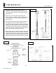
8. Connect the accessory power cord or hard wire
connector to unit chassis’s connector (refer to Fig
6).
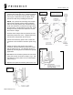
9. Clamp the power cord harness and conduit
connector asy with chassis’s junction box cutout
slot as shown of Fig 3. The clamping device is
applied by screwing down the locknut and spacers
application.
10. Reinstall the unit chassis’s junction box and cover
using all 6 screws as shown on Step 1 Fig 1. Use
wire clamp to secure power cord to unit basepan
(refer to Fig 7).
11. Replace front panel and restore power to the unit.
Fig 5
Fig 6
Connection to unit
chassis connector
Fig 7