
Installation and Operation Manual (2019, 2020, 2021)
ManualsBrandsFriedrich ManualsAir Conditioners14,500 BTU Smart Packaged Terminal Air Conditioner with FriedrichLink Energy Management Thermostats, Heat Pump, Antimicrobial Air Filters, Electronic Defrost Control, Tangential Blower Wheel, Room Freeze Protection, Fresh Air Damper, Slinger Ring Technolo

RT7
Manual Thermostat
The Friedrich RT7 is a non-
programmable electronic thermostat,
which can be used with the following
heating/cooling applications:
• Single Stage Heat - Cool PTAC Units
• Singe Stage Heat Pump PTAC Units
with or without Electric Heat
Installation and Operation Guide
• Input Voltage: 19 to 30 VAC
• Output Rating: Max. 1.5A per terminal (3A total)
• Temperature Control: 45°F to 90°F (7°C to 32°C)
• Temperature Accuracy: ± 1°F (± 0.5°C)
Specications
• This thermostat is for LOW voltage applications only.
• Turn OFF electricity to all heating and cooling components.
• All wiring must conform to applicable local and national building and electrical codes
and ordinances.
Safety Information
• Thermostat
• J-Box mounting plate/
decorative trim plate
• J-box mounting screws
• Dry wall anchors and mounting screws
• Wiring labels
• GL to GH Jumper wire
Included in Package
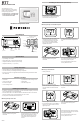
Parts Diagram
Opening
notch
(underneath)
Up button
Fan
Slide
Switch
Down button
Mode
Slide
Switch
Mounting directly on wall with trim plate
• If new mounting holes are needed, mark
the placement of the new horizontal
mounting holes through the trim plate
base. Using a 3/16" drill bit, drill the
holes you have marked and insert the
supplied wall anchors.
• Feed the wires through the back housing
of the thermostat and then snap the
back housing to the trim plate
• Your thermostat base should now be
securelyxedtothewall
• Feed the wires through the hole in the
trim plate and screw the trim plate to the
wall
• Useaatheadscrewdrivertoseparate
the front and back housing of the
thermostat
• If painting or construction is still ongoing, cover the thermostat completely or wait until
work is complete before mounting thermostat.
• Mountthethermostatonaninsidewallaboutvefeetabovetheoorinanareathat
hasgoodcirculationbutisnotdirectlyaectedbyaventorduct.
• Ensure power is switched OFF at the PTAC unit
Installing the Thermostat
Mounting directly on the wall
• Useaatheadscrewdrivertoseparate
the front and back housing of the
thermostat
• If new mounting holes are needed, mark
the placement of the new mounting holes
through the thermostat base. Using a
3/16" drill bit, drill the holes you have
marked and insert the supplied wall
anchors.
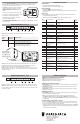
F
C
COOL HEAT
WAITOFF
E
RESET
Air Temp
Thermostat
mode
Fan status
indicator
Half degree for Celsius
Electric / Auxiliary Heat
Set tempLock
Status
Minimumo
time indicator
Heating/cooling
indicator
53624
Installing the Thermostat (continued)
• Feed the wires through the hole in the
back housing of the thermostat and then
screw the back housing to the wall
Mounting on Junction Box
• Install junction box
• Insert mounting screw into top of
junction box until there is approximately
1/8" gap between the screw head and
the wall
• Useaatheadscrewdrivertoseparate
the front and back housing of the
thermostat
• Feed the wires through the hole in the
trim plate and hang the trim plate on the
top screw
• Feed the wires through the back housing
of the thermostat and then snap the back
housing to the trim plate
• Your thermostat base should now be
securelyxedtothewall
• Insert and tighten the lower screw
• Ensurethattrimplateissecurelyttedto
the wall. If not, release lower screw and
tighten top screw.