Installation & Operation Manual Hazardgard ® Hazardous Location Room Air Conditioner Equipment is certified in accordance with: ISA 12.12.01 and NFPA 70-10 (National Electric Code) Article 501 Class I , Div. 2 Groups A,B,C,& D ATEX* Article 505 Class I , Zone 2, Groups IIA IIB + H and IIC IECEx* Ex ec nA nC IIC T Gc IECEx UL15.
Table of Contents Operation and Care Instructions Your Safety and the safety of others............................................................................................................................................. 2 General Instructions...................................................................................................................................................................... 3 Filter Information...........................................................................
Congratulations! Thank you for your decision to purchase the Friedrich Hazardgard (Hazardous Duty Room Air Conditioner). Your new Friedrich has been carefully engineered and manufactured to give you many years of dependable, efficient operation, maintaining a comfortable temperature and humidity level. Many extra features have been built into your unit to assure quiet operation, the greatest circulation of cool, dry air, and the most economic operation.
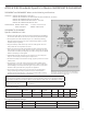
Filter Information The filter in your Friedrich removes dust, pollen and other impurities from the air as they are drawn through the unit. The filter is permanent and reusable, and has a germicidal treatment which is not affected by periodic washing. A clogged, dirty filter reduces the air flow through the unit and reduces its efficiency. You should check the filter every seven to ten days, depending on the amount your unit is used.
Hazardgard Special Features • Permanent Split-Capacitor, totally enclosed fan motor to assure efficient operation even under adverse electrical conditions. • Motor has a special stainless steel shaft to resist corrosion and a hermetically sealed overload for arc-free operation. • High capacity compressor with internal hermetically sealed overload. • Contains transient voltage suppressor to protect controls against transient voltage spikes. Provides solid state switches for arc- free operation.
ATEX & ICEX Standards Specific to Models SH20N50AT & SH24N30AT SH20N50AT and SH24N30AT Adhere to the following certifications: CERTIFIED PER STD. NO. ANSI/ISA 12.12.01,2013 PER STD. NO. IEC 60079-0, 6th Edition PER STD. NO. IEC 60079-15, 4th Edition PER STD. NO. CAN/CSA C22.2 NO. 213-M1987 PER STD. NO. CENELEC EN 60079-0: 2012 + A11: 2013 PER STD. NO. CENELEC EN 60079-15: 2010 CERTIFICATION DEMKO 15 ATEX 1364X IECEX UL15.
Installation Instructions Models SH15, SH20 and SH24 NOTE: THIS MANUAL INCLUDES INSTALLATION INSTRUCTIONS FOR BOTH WINDOW MOUNT AND THROUGH- THE WALL INSTALLATIONS WARNING Explosion Hazard Electrical Shock Hazard Electrically connect unit in accordance with NEC Code Article 501. Failure to do so can result in death, explosion, fire or electrical shock Electrical Requirements ALL FIELD WIRING MUST MEET THE REQUIREMENTS OF THE NATIONAL ELECTRICAL CODE (ANSI/NFPA 70) ARTICLE 501.
Window Mount Installation Hardware ITEM No. DESCRIPTION QTY. SHELL MOUNTING PARTS 1 SUPPORT BRACKET 2 2 SCREW, 10 - 24 x 1” HEX HEAD 4 3 10 - 24 FLAT WELDNUT 4 4 SCREW, SHEET METAL #12A x 2” 7 WINGBOARD ANGLE MOUNTING 5 WINGBOARD ANGLE, TOP 1 6 WINGBOARD ANGLE, SIDE 2 7 SCREW, SHEET METAL #8A x 3/8” 2 WINGBOARD MOUNTING PARTS 8 WINGBOARD (MASONITE) 1 9 J TYPE SPEED NUT 4 10 WINGBOARD CLIP (SPRING STEEL) 4 11 SCREW. #8A x 1/2” PHILLIPS TRUSS HD.
Unpacking The Unit STEP 1 Cut the packing straps and remove box pulling it up, remove corner-post and protective packing, conserve the fiberboard wing board in a safe place, it will be used later. Figure 2 STEP 2 Remove decorative plastic return air grille to a safe area away from the unit. STEP 3 Remove the installation hardware, two gaskets from beneath the unit, and place them in a safe area away from the unit.
Unpacking The Unit STEP 5 Remove and discard the two retainer screws and plastic bushings located at the rear of the unit. (Figure 5) Figure 5 STEP 6 While an assistant holds the cabinet stationary, use the hand pull at the front of the base pan (see Figure 6) to pull the chassis out of the cabinet. Figure 6 STEP 7 Remove white foam blocks used to restrain the compressor during shipment (if included). Also remove junction box from under fan motor.
Installation: Outdoor/Indoor Clearances Figure 8 Figure 9 11
Shell Installation: Through-the-wall Installations (as unit is shipped) WARNING Falling Object Hazard Not following Installation Instructions for mounting your air conditioner can result in property damage, injury, or death. Wall Preparation The maximum wall thickness permissible without special construction is determined by the model size to be installed. THE OUT- SIDE CABINET CONDENSER AIR INTAKE LOUVERS MUST NOT BE BLOCKED BY EXTENDING INSIDE THE WALL AREA.
Figure 12 CAULK ALL SIDES INSIDE AND OUTSIDE FRAME WALL CONSTRUCTION CAULK ALL SIDES INSIDE AND OUTSIDE CABINET BRICK VENEER CONSTRUCTION CABINET SHIM TO FILL IN VOID AT THE TOP AND SIDES WITH WOOD AS REQUIRED SHIM TO FILL IN VOID AT THE TOP AND SIDES WITH WOOD AS REQUIRED Figure 14 Figure 13 CAULK ALL SIDES INSIDE AND OUTSIDE SOLID MASONRY CONSTRUCTION CABINET MORTAR 13
STEP 3 Slide the cabinet into the hole far enough to allow the guide-channel of the sill plate to contact the inside wall surface (See Figure 15). STEP 4 Drill three (3) 5/32” diameter pilot holes through holes in sill-plate into the framing and install three (3) #12 x 2” long screws (Item #4) (See Figure15). NOTICE Instructions for mounting sleeve with slope must be observed to prevent entry of water into room. Potential property damage can occur if instructions are not followed.
Shell (Cabinet) Preparation for Installation STEP 1 Remove still plate and bend the taps up and reinstall 4” back from original shipping position. Move shell guides 4” forward (to the forward-most hole in the shell rail). See (DETAIL 16-A). STEP 2 Take the side angles (item #6) and engage its loops in the tabs (both sides) of the sill plate. (DETAIL 16-A). STEP 3 Take the top Flange (item #5) and engage its tabs in the top loops of the side flanges (DETAIL 16-B).
Shell Installation: Sash Window Installations WARNING Falling Object Hazard Not following Installation Instructions for mounting your air conditioner can result in property damage, injury, or death. STEP 1 Check the window sill and frame to be sure they are in good condition and firmly anchored to the wall. Repair if necessary. STEP 2 CABINET MOUNTING: Raise the lower window sash 1/4” more than the height of the cabinet.
Typical Installation: Sill Plate The illustrations below show a standard frame construction installation as well as some suggested ways of adapting the support bracket to thick walls and large brick ledges. NOTICE Instructions for mounting sleeve with slope must be observed to prevent entry of water into room. Failure to follow instructions can result in property damage.
Typical Installation: Sill Plate (cont.
Figure 23 STEP 4 CUT WINGBOARD PANELS: Measure and cut the wingboard panels from the supplied masonite (Item #8) to fit the spaces between the side window channels and the sides of the cabinet (See Figure 23). NOTE: AFTER CUTTING PANELS, MAKE A TRIAL TEST TO SEE IF THEY FIT THE SPACE WITH ABOUT 1/8” CLEARANCE BEFORE GOING TO STEP 5.
Figure 25 SECTION A -A TOP OF CABINET WINDOW JAM CLIP (ITEM10) PLACE WINGBOARD PANEL IN WINDOW JAM TO COMPRESS THE SPRINGS INSIDE THE RUNNERS, AND SWING THE PANEL INTO PLACE INDICATED BY THE DOTTED LINE. STEP 6 INSTALL SIDE WINGBOARD PANELS: Be sure that the cabinet has been secured to the window sill and the outside support brackets have been installed as shown in (Figures 19 and 20) on Page 17. Raise the window sash and install the right and left side wingboard panels (See Figure 25).
Chassis Wiring and Preparation (Non ATEX) PROVIDED HARDWARE 1 JUNCTION BOX 2 MOUNTING LEGS 2 LEG SCREWS 2 HOLE COVERS 1 STAINLESS STEEL GROUND SCREW 2 SCREWS 1 SHEET METAL SCREW STEP1 Remove the junction box, cover and screws from the shipping position underneath the fan motor (See Figure 7). Install one junction box mounting leg in the upper left position facing the rear of the junction box.
Chassis Wiring and Preparation STEP 3 Insert all wires into the rear of the junction box and thread the box onto the threaded bushing until tight. Figure 29 STEP 4 Back off clockwise until the junction box is vertical with the mounting leg at the upper–right position facing the box opening. Be sure that the shell can slide between this box and the chassis. Figure 30 STEP 5 Insert the unit in the shell see Page 25 for help, be sure that the shell can slide between junction box and the chassis.
Chassis Wiring and Preparation (ATEX & IECEx Models) STEP1 Remove the junction box from the shipping position underneath the fan motor (Figure 7). Install junction box mounting legs to back of the junction box using 4 provided machine screws (Figure 32-1). Mount junction box to provided holes on side of air conditioner sleeve using 4 provided sheet metal screws and 4 serrated washers. Ensure serrated washers are between legs of junction box and painted metal sleeve (figure 32-2).
Chassis Wiring and Preparation (ATEX & IECEx Models) STEP 4 Complete junction box wiring, cover and tighten cover screws (Figure 34-6) to prevent ingress from dust and moisture. NOTE: Per EN/IEC 60079-0, external grounding or earthing may be necessary. If required, use provided external ground clamp which can accept two cables of up to 6mm (Figure34-7).
Chassis Installation STEP1 Slide the chassis into the cabinet stopping approximately 3” from full insertion. Stuff the chassis seal gasket (Item #12) one inch deep between the chassis and the cabinet (Figure 36). Begin at either bottom corner and go up the side, across the top, and down the opposite side. Make sure that the gasket is behind the conduit connector (furthest from you). Push the chassis into the shell the remaining distance so that the plastic front shrouds the front edge of the shell.
STEP 2 Be sure that the filter is in place then install the return air grille (Figure 37). The top of the return air grille can be butted against the bottom of the discharge plenum. Snap the grille into place by pushing the grille up and onto the unit’s latches at the bottom. (See Detail 37-4).
Maintenance Checklist Won’t Cool If the unit operates, but doesn’t cool, check to see that the controls are properly set. Inspect the filter and if needed, clean it thoroughly. Check to see if the chassis seal gasket is installed (refer to installation instructions). Won’t Run If the unit does not operate at all, check that the power supply connections are present and tight. Check for blown fuses or tripped circuit breakers. Replace blown fuses with the proper size time-delay fuse.
Friedrich Air Conditioning Company 10001 Reunion Place, Suite 500 San Antonio, TX 78216 800.541.6645 www.friedrich.com HAZARDGARD® ROOM AIR CONDITIONERS LIMITED WARRANTY LIMITED ONE YEAR PARTS WARRANTY 1. Limited warranty – One year. Friedrich warrants that it will provide a replacement for any part of this HazardGard Room Air Conditioner found defective in material or workmanship for a period of one (1) year from the date of original purchase. 2. Limited warranty – One year.
Friedrich Air Conditioning Company 10001 Reunion Place, Suite 500 San Antonio, TX 78216 800.541.6645 www.friedrich.com INTERNATIONAL LIMITED WARRANTY TERMS OF LIMITED WARRANTY Friedrich Air Conditioning Co. warrants to the original purchaser that this Friedrich Air Conditioner is free from defects as to material and workmanship.
Friedrich Air Conditioning LLC 10001 Reunion Place, Suite 500 San Antonio, Texas 78216 800.541.6645 www.friedrich.
Manual de instalación y uso Hazardgard ® Unidad de aire acondicionado para uso en lugares peligrosos El equipo está certificado conforme a: ISA 12.12.01 y NFPA 70-10 (National Electric Code) Artículo 501 Clase I, División 2 Grupos A, B, C y D ATEX* Artículo 505 Clase I, Zona 2, Grupos IIA IIB + H y IIC IECEx* Ex ec nA nC IIC T Gc IECEx UL15.
Índice Table of Contents Instrucciones usoInstructions y mantenimiento Operation andde Care Su seguridad y la de los demás..............................................................................................................................................................................................................2 Your Safety and the safety of others ............................................................................................................................................
Felicitaciones Gracias por la compra de la unidad de aire acondicionado Friedrich Hazardgard para uso en lugares peligrosos. Su nueva unidad Friedrich ha sido cuidadosamente diseñada y fabricada para brindarle muchos años de funcionamiento confiable y eficiente, a fin de mantener un nivel agradable de temperatura y humedad. Se han incorporado en la unidad muchas características adicionales para garantizar un funcionamiento silencioso y económico con una mayor circulación de aire seco y fresco.
Información sobre el filtro El filtro de su unidad Friedrich elimina el polvo, el polen y otras impurezas del aire a medida que son aspirados por el equipo. El filtro es permanente, reutilizable y tiene un tratamiento germicida que no se ve afectado por el lavado frecuente. Un filtro sucio y obstruido reduce el flujo de aire a través de la unidad y disminuye su eficiencia. Deberá examinar el filtro cada siete a diez días según la frecuencia de uso de la unidad. Limpie el filtro periódicamente.
Características especiales del modelo Hazardgard • Motor del ventilador totalmente sellado y con capacitores de separación permanente para garantizar un funcionamiento eficiente, incluso en condiciones eléctricas adversas. • Serpentines de cobre con aletas hidrófilas revestidas en aluminio. • El motor tiene un eje especial de acero inoxidable para evitar la corrosión y un control de sobrecarga herméticamente sellado para un funcionamiento sin problemas.
Normas ICEX y ATEX específicas para los modelos SH20N50AT y SH24N30AT Los modelos SH20N50AT y SH24N30AT se adhieren a las siguientes certificaciones: CERTIFICADO CONFORME A LA NORMA N.° ANSI/ISA 12.12.01, 2013 CONFORME A LA NORMA N.° IEC 60079-0, 6.ª edición CONFORME A LA NORMA N.° IEC 60079-15, 4.ª edición CONFORME A LA NORMA N.° CAN/CSA C22.2 N.° 213-M1987 CONFORME A LA NORMA N.° CENELEC EN 60079-0: 2012 + A11: 2013 CONFORME A LA NORMA N.
Instrucciones de instalación Modelos SH15, SH20 y SH24 NOTA: ESTE MANUAL INCLUYE LAS INSTRUCCIONES PARA LA INSTALACIÓN TANTO DEL MODELO PARA MONTAJE EN VENTANA COMO PARA MONTAJE EN PARED ADVERTENCIA WARNING Riesgo de explosión Explosion Hazard Riesgo de descarga Electrical Shockeléctrica Hazard Electrically connect unit in accordance with NEC Conecte la unidad al sistema eléctrico conforme al artículo Code to do so can result in muertes, 501 delArticle NEC. 501.
Equipo de instalación para montaje en ventana ELEMENTO N.° CANTIDAD DESCRIPCIÓN ELEMENTO N.° 2 PIEZAS DE MONTAJE DEL ARMAZÓN 1 SOPORTE ANGULAR 2 2 TORNILLO 10-24 DE 1 in (25 mm) CON CABEZA HEXAGONAL 4 3 TUERCA SOLDADA PLANA 10-24 4 4 TORNILLOS METÁLICOS N.º 12A de 2 in (51 mm) 7 ELEMENTO N.° 3 ÁNGULO DE MONTAJE DEL PANEL DE ALAS 5 ÁNGULO DEL PANEL DE ALAS, SUPERIOR 1 6 ÁNGULO DEL PANEL DE ALAS, LATERAL 2 7 TORNILLO METÁLICO N.
Desembalaje de la unidad PASO 1 Corte las cintas de embalaje y deslice la caja hacia arriba para quitarla. Quite el poste de la esquina y el embalaje protector. Conserve el ala lateral de fibra en un lugar seguro (la usaremos más tarde). Figura 2 Figure PASO 2 Retire la rejilla de aire de retorno decorativa plástica y manténgala en un lugar seguro, alejado de la unidad. PASO 3 Retire el equipo de instalación y las dos juntas que se encuentran debajo de la unidad.
Desembalaje de la unidad PASO 5 Retire y descarte los dos tornillos de fijación y los casquillos plásticos que se encuentran en la parte trasera de la unidad. (Figura 5) Figura Figure 5 PASO 6 Mientras un ayudante sostiene el gabinete, utilice la manija de la parte frontal de la bandeja base (vea la figura 6) para extraer el chasis del gabinete. Figure 6 Figura PASO 7 Retire los bloques de espuma que inmovilizan el compresor durante el transporte de la unidad (si se incluye).
Instalación: espacios interiores y exteriores Figura 8 Figura 9 11
Instalación del armazón: instalaciones de pared (tal como viene la unidad de fábrica) WARNING ADVERTENCIA Riesgo de caída de objetos Falling Object Hazard Si se siguen las instrucciones Notno following Installation Instructionsde instalación for mounting yourdel airaire conditioner can para el montaje acondicionado, pueden result in property damage, injury, or lesiones o producirse daños en la propiedad, death. muertes.
Figura 12 IMPERMEABILICE CAULK ALL TODOS SIDES LOS LATERALES, INSIDE AND INTERNOS OUTSIDE Y EXTERNOS REALIZACIÓN DE MARCO EN LA PARED CAULK ALL IMPERMEABILICE SIDES INSIDE TODOS LOS AND OUTSIDE LATERALES, INTERNOS Y EXTERNOS GABINETE CABINET COLOQUE SHIM UNA CUÑA DEINMADERA TO FILL VOID AT EN EL ESPACIO VACÍO EN LA PARTE THE TOP AND SIDES WITH SUPERIORWOOD Y EN LOS LATERALES, AS REQUIRED SEGÚN SEA NECESARIO Figura Figura 14 14 Figura13 13 Figura IMPERMEABILICE CAULK ALL TODOS LOS LATERALES, SIDES IN
PASO 3 Deslice el gabinete por el hueco lo más que pueda para permitir que el canal guía de la placa de alféizar entre en contacto con la superficie de la pared interna (vea la figura 15). PASO 4 Perfore tres (3) orificios piloto de 5/32 in de diámetro a través de los orificios de la placa de alféizar hasta el marco y coloque tres (3) tornillos largos n.° 12 de 2 in (elemento 4) (vea la figura 15).
Preparación del armazón (gabinete) para su instalación PASO 1 Retire la placa fija, doble los grifos hacia arriba y vuelva a instalar 4 ”desde la posición original de envío. Mueva las guías de la carcasa 4 “hacia adelante (hasta el orificio más hacia adelante en el riel de la carcasa). Vea el DETALLE 16-A. PASO 2 Tome los ángulos laterales (elemento 6) y conecte los bucles en las lengüetas (ambos lados) de la placa de alféizar. (DETALLE 16-A).
Instalación del armazón: instalación del bastidor de la ventana ADVERTENCIA WARNING Riesgo de caída de objetos Falling Object Hazard Notno following Installation Instructions de instalación para Si se siguen las instrucciones formontaje mountingdel your airacondicionado, conditioner can pueden producirse el aire result inen property damage,lesiones injury, or o muertes. daños la propiedad, death. PASO 1 Verifique que el bastidor y el marco de la ventana estén en buen estado y fijos firmemente a la pared.
Instalación típica: placa de alféizar En las siguientes ilustraciones figura la instalación de la construcción del marco estándar y algunas recomendaciones sobre cómo adaptar el soporte a paredes gruesas y salientes de ladrillo gruesas. AVISO Se deben seguir las instrucciones de montaje del manguito con declive para evitar el ingreso de agua a la sala. El incumplimiento de las instrucciones puede provocar daños a la propiedad.
Instalación típica: placa de alféizar (continuación) Figura 21 Figura 22 18
Figura 23 PASO 4 CORTE DE PANELES DE ALAS: Mida y corte los paneles de ala de la masonita suministrada (elemento 8) de forma que se ajusten a los espacios entre los canales de la ventana lateral y los laterales del gabinete (vea la figura 23). NOTA: DESPUÉS DE CORTAR LOS PANELES, HAGA UNA PRUEBA PARA VER SI SE AJUSTAN AL ESPACIO Y QUEDA UN ESPACIO LIBRE DE APROXIMADAMENTE 1/8 in ANTES DE CONTINUAR AL PASO 5.
Figura 25 PASO 6 INSTALE LOS PANELES DE ALAS LATERALES: Asegúrese de que el gabinete se haya fijado al antepecho de la ventana y de que los soportes exteriores se hayan instalado como se muestra en las figuras 19 y 20 en la página 17. Levante el bastidor de la ventana e instale los paneles de alas derecho e izquierdo. (Vea la figura 25).
Cableado y preparación del chasis (modelo que no es ATEX) TORNILLERÍA SUMINISTRADA 1 CAJA DE CONEXIONES 2 PATAS DE MONTAJE 2 TORNILLOS DE PATA 2 CUBIERTAS DE HUECOS 1 TORNILLO CON CONEXIÓN A TIERRA DE ACERO INOXIDABLE 2 TORNILLOS 1 TORNILLO METÁLICO PASO 1 Quite la caja de conexiones, la cubierta y los tornillos de la posición de envío debajo del motor del ventilador (vea la figura 7).
Cableado y preparación del chasis PASO 3 Inserte todos los cables en la parte posterior de la caja de conexiones y coloque la caja en el buje roscado hasta que quede ajustada. Figura 29 29 Figure PASO 4 Muévala hacia la derecha hasta que la caja de conexiones quede en posición vertical con la pata de montaje en la posición superior derecha orientada hacia la apertura de la caja. Asegúrese de que el armazón pueda deslizarse entre esta caja y el chasis.
Cableado y preparación del chasis (modelos ATEX e IECEx) PASO 1 Quite la caja de conexiones de la posición de envío debajo del motor del ventilador (figura 7). Instale las patas de montaje de la caja de conexiones en la parte posterior de esta con los 4 tornillos para metales suministrados (figura 32-1). Instale la caja de conexiones sobre los orificios en el lateral del manguito del aire acondicionado con los 4 tornillos metálicos suministrados y las 4 arandelas dentadas.
Cableado y preparación del chasis (modelos ATEX e IECEx) PASO 4 Complete el cableado de la caja de conexiones, cúbrala y ajuste los tornillos de la tapa (figura 34-6) para evitar el ingreso de polvo y humedad. NOTA: En conformidad con EN/IEC 60079-0, es posible que deba realizarse una conexión a tierra. Si es necesario, use la abrazadera de conexión a tierra provista que puede admitir dos cables de hasta 6 mm (figura 34-7).
Instalación del chasis PASO 1 Deslice el chasis hacia el tope del gabinete aproximadamente hasta una distancia de 3 in de la inserción completa. Coloque la empaquetadura de sellado del chasis (elemento 12) a una pulgada de profundidad entre el chasis y el gabinete (figura 36). Comience en la esquina inferior y suba por el lateral, por la parte superior y hacia abajo del lado opuesto. Asegúrese de que la empaquetadura se encuentre detrás del conector del conducto (más alejado de usted).
PASO 2 Asegúrese de que el filtro se encuentre en su lugar e instale la rejilla de aire de retorno (figura 37). La parte superior de la rejilla de aire de retorno puede empalmarse a la parte inferior de la cámara de descarga. Coloque la rejilla en su lugar empujándola hacia arriba y hacia los pestillos de la unidad en la parte inferior. (Vea el detalle 37-4).
Lista de control de mantenimiento No enfría Si la unidad funciona, pero no enfría, asegúrese de que los controles tengan el ajuste correcto. Inspeccione el filtro y, de ser necesario, límpielo cuidadosamente. Compruebe si está instalada la junta de sellado del chasis (consulte las instrucciones de instalación). No funciona Si la unidad no funciona en absoluto, verifique el ajuste de las conexiones al suministro eléctrico. Compruebe si hay fusibles quemados o interruptores automáticos.
Friedrich Air Air Conditioning Friedrich ConditioningCompany Company 10001 Reunion Reunion Place, Place, Suite Suite 500 500 10001 San Antonio, Antonio, TX TX 78216 78216 San 800.541.6645 800.541.6645 www.friedrich.com www.friedrich.com HAZARDGARD HAZARDGARD® UNIDADES AIRE ACONDICIONADO ROOMDE AIR CONDITIONERS GARANTÍA LIMITADA LIMITED WARRANTY GARANTÍA PIEZAS DE UN AÑO LIMITED DE ONE YEAR LIMITADA PARTS WARRANTY 1.1.Garantía año. year.
Friedrich Air Air Conditioning Company Friedrich Conditioning Company 10001 Reunion Place, Suite 10001 Reunion Place, Suite 500500 Antonio, TX 78216 SanSan Antonio, TX 78216 800.541.6645 800.541.6645 www.friedrich.com www.friedrich.com GARANTÍA LIMITADA INTERNATIONAL INTERNACIONAL LIMITED WARRANTY TÉRMINOS DEOF LALIMITED GARANTÍA LIMITADA TERMS WARRANTY Friedrich que este acondicionador aire Friedrich estáfrom libredefects de defectos cuanto FriedrichAir AirConditioning ConditioningCo. Co.
Friedrich Air Conditioning LLC Friedrich Air Conditioning Company 10001 Reunion Place, Suite 500 10001 Reunion Place, Suite 500 San Antonio, Texas 78216 San Antonio, Texas 78216 800.541.6645 800.541.6645 www.friedrich.com www.friedrich.
Manuel d'installation et d'utilisation Hazardgard ® Climatiseur individuel pour les lieux dangereux Le matériel est certifié conformément à : ISA 12.12.01 et NFPA 70-10 (Code national de l’électricité) Article 501 Classe I , Div. 2 Groupes A,B,C et D ATEX* Article 505 Classe I , Zone 2, Groupes IIA IIB + H et IIC IECEx* Ex nA ec nC IIC T Gc IECEx UL15.
Table matières Table des of Contents Fonctionnement et entretien Operation and Care Instructions Votre sécuritéand et celle autres. ..........................................................................................................................................................................................................2 Your Safety the des safety of others ...........................................................................................................................................
Félicitations! Merci pour votre décision d'acheter le Friedrich Hazardgard (Climatiseur individuel pour les tâches risquées). Votre nouveau Friedrich a été soigneusement conçu et fabriqué pour vous donner de nombreuses années de fonctionnement fiable, efficace, tout en gardant un niveau de température et d'humidité agréables.
Informations relatives au filtre Le filtre à l’intérieur de votre Friedrich élimine la poussière, le pollen et les autres impuretés de l'air quand ils sont extraits de l’appareil. Le filtre est permanent et réutilisable, et a un traitement germicide qui n'est pas affecté par le lavage périodique. L'encrassement et les saletés du filtre réduisent le débit d'air dans appareil ainsi que son efficacité. Vous devriez vérifier le filtre tous les sept à dix jours, selon le degré d’utilisation de votre appareil.
Caractéristiques propres à Hazardgard • Condensateur auxiliaire permanent, moteur avec ventilation complètement fermé pour assurer un fonctionnement efficace même dans des conditions électriques difficiles. • Le moteur a un axe en acier inoxydable résistant à la corrosion et une surcharge scellée hermétiquement pour un fonctionnement sans problèmes de l’arc. • Compresseur haute capacité avec surcharge interne scellée hermétiquement.
Normes ATEX et ICEX propres aux modèles SH20N50AT et SH24N30AT SH20N50AT et SH24N30AT respectent les certifications suivantes : CERTIFIÉ SELON LA NORME. N° ANSI/ISA 12.12.01,2013 SELON LA NORME N° IEC 60079-0, 6e Édition SELON LA NORME N° IEC 60079-15, 4e Édition SELON LA NORME N° CAN/CSA C22.2 N° 213-M1987 SELON LA NORME N° CENELEC EN 60079-0: 2012 + A11 : 2013 SELON LA NORME N° CENELEC EN 60079-15 : 2010 CERTIFICATION DEMKO 15 ATEX 1364X IECEX UL15.
Instructions d'installation Modèles SH15, SH20 et SH24 REMARQUE : CE MANUEL COMPREND DES INSTRUCTIONS D'INSTALLATION À LA FOIS POUR LE SUPPORT DES FENÊTRES ET LES INSTALLATIONS À TRAVERS LES MURS AVERTISSEMENT WARNING Risque d'explosion Explosion Hazard Risque de choc électrique Electrical Shock Hazard Electrically connect unit in accordance with NEC à l’Article 501 Brancher électriquement l’appareil conformément Code Article 501. Failure de to do can result in du CNE.
Matériel d’installation pour le support de la fenêtre N° de référence DESCRIPTION QTÉ RÉFÉRENCE N° 2 PIÈCES DE MONTAGE DE L’ARMOIRE 1 PATTE DE SUPPORT 2 2 VIS, À TÊTE HEXAGONALE 10 - 24 DE 1 PO 4 3 ÉCROU PLAT 10 - 24 4 4 VIS, TÔLE N°12A DE 2 PO 7 RÉFÉRENCE N° 3 PROFILÉ DE MONTAGE DU PANNEAU LATÉRAL 5 PROFILÉ DU PANNEAU LATÉRAL, SUPÉRIEUR 1 6 PROFILÉ DU PANNEAU LATÉRAL, CÔTÉ 2 7 VIS, TÔLE N°8A DE 3/8 PO 2 RÉFÉRENCE N° 4 PIÈCES DE MONTAGE DU PANNEAU LATÉRAL 8 PANNEAU LATÉRAL (MASONITE) 1
Déballage de l’appareil ÉTAPE 1 Coupez les sangles d'emballage et enlevez la boîte en la tirant vers le haut, enlevez la tige de coin et l’emballage de protection, conservez le panneau latéral dans un endroit sûr, il sera utilisé plus tard. Figure 2 ÉTAPE 2 Enlevez le plastique décoratif de la grille d'air de retour et rangez-le dans un endroit sûr loin de l'appareil. ÉTAPE 3 Enlevez le matériel d'installation, les deux joints sous l'appareil et placez-les dans un endroit sûr loin de l'appareil.
Déballage de l’appareil ÉTAPE 5 Enlevez et jetez les deux vis de fixation et les douilles en plastique situées à l'arrière de l'appareil. (Figure 5) Figure 5 ÉTAPE 6 Pendant qu'un assistant tient l’armoire immobile, utilisez la main pour tirer sur l'avant du plateau de base (voir la Figure 6) afin de retirer le châssis de l'armoire. Figure 6 ÉTAPE 7 Enlevez les blocs de mousse blanche utilisés pour contenir le compresseur au cours de l'expédition (si inclus).
Installation : Jeux extérieurs/intérieurs Figure 8 Figure 9 11
Installation de l’armoire : Installations à travers le mur (lors de l’expédition de l’appareil) AVERTISSEMENT WARNING Falling Object Hazard Risque de chute d’objet Ne respecter les Instructions Notpas following Installation Instructionsd’installation pour formontage mountingde your air conditioner le votre climatiseurcan peut entraîner des result inou property damage, injury, or voire mortelles. dégâts des blessures graves, death.
Figure 12 CALFEUTREZ CAULK ALL TOUS LES SIDES CÔTÉS INSIDE AND DE FAÇON OUTSIDE ÉTANCHE CONSTRUCTION DE L’OSSATURE DU MUR CALFEUTREZ CAULK ALL SIDES INSIDE TOUS LES AND OUTSIDE CÔTÉS DE FAÇON ÉTANCHE ARMOIRE CABINET CABINET ARMOIRE CONSTRUCTION DU PLACAGE EN BRIQUE ARMOIRE CABINET CALEZ POUR REMPLIR SHIM TO FILL IN VOID AT THE TOP AND SIDES WITH LE VIDE EN HAUT ET SUR WOOD AS REQUIRED LES CÔTÉS AVEC DU BOIS TEL QUE REQUIS CALEZ POUR REMPLIR SHIM TO FILL IN VOID AT LE HAUT ETWITH SUR THEVIDE TOPEN A
ÉTAPE 3 Faites glisser l'armoire dans le trou à une distance suffisante pour permettre le canal de guidage du lisse bas d’entrer en contact avec la surface intérieure du mur (Voir Figure 15).
Préparation de l’armoire (coque de protection) pour l’installation ÉTAPE 1 Retirez la plaque d’immobilisation et pliez les robinets vers le haut et réinstallez à 4 po de la position d’expédition d’origine. Déplacer les guides de coque de 4 po vers l’avant (jusqu’au trou le plus en avant du rail de coque). Voir (DÉTAIL 16-A). ÉTAPE 2 Prenez les profilés latéraux (référence N° 6) et insérez ses boucles dans les taquets (des deux côtés) du lisse bas. (DÉTAIL 16-A).
Installation de l’armoire : Installations de la fenêtre à guillotine AVERTISSEMENT WARNING Risque de chute d’objet Falling Object Hazard Ne respecter les Instructions Notpas following Installation Instructionsd’installation pour le montage climatiseur for mounting yourde air votre conditioner can peut result in property damage, injury, or entraîner des dégâts ou des blessures graves, death.mortelles.
Installation typique : LISSE BAS Les illustrations ci-dessous montrent une installation de la construction d’un châssis standard ainsi que certaines solutions suggérées pour adapter la patte de support aux murs épais et de grandes pièces d’appui en brique. REMARQUE Les instructions de montage du manchon avec pente doivent être observées pour éviter toute pénétration d'eau dans la pièce. Le non-respect des instructions peut entraîner des dégâts matériels.
Installation typique : Lisse bas (suite) Figure 21 Figure 22 18
Figure 23 ÉTAPE 4 COUPER LES PANNEAUX LATÉRAUX : Mesurez et coupez les panneaux latéraux du masonite fourni (Référence N°8) pour mettre en place les espaces entre les chaînes latérales de la fenêtre et les côtés de l'armoire (Voir Figure 23). REMARQUE : APRÈS LA DÉCOUPE DES PANNEAUX, FAITES UN TEST D'ESSAI POUR VOIR S'ILS CORRESPONDENT À L'ESPACE AVEC UN JEU D'ENVIRON 3 MM (1/8 PO) AVANT D'ALLER À L'ÉTAPE 5.
Figure 25 SECTION A –A ÉTAPE 6 INSTALLER LES PANNEAUX LATÉRAUX : Assurez-vous que l’armoire a été fixée à l'appui de fenêtre et que les pattes de support extérieurs ont été installées comme indiqué aux (Figures 19 et 20) à la Page 17. Relevez le châssis de fenêtre et installez les panneaux latéraux droit et gauche (Voir la Figure 25).
Préparation et câblage du châssis (Non ATEX) MATÉRIEL FOURNI PROVIDED HARDWARE 1 BOÎTIER DE BOX JONCTION JUNCTION 2 PATTES DE FIXATION MOUNTING LEGS 2 VIS PATTE LEGDE SCREWS 2 COUVERCLES HOLE COVERSDE TROU 1 V IS DE MASSE EN STAINLESS STEEL GROUND SCREW ACIER INOXYDABLE SCREWS 2 VIS 1 VIS À TÔLE SHEET METAL SCREW ÉTAPE 1 Enlevez le boîtier de jonction, le couvercle et les vis de la position d'expédition sous le moteur du ventilateur (voir Figure 7).
Préparation et câblage du châssis ÉTAPE 3 Insérez tous les fils à l'arrière du boîtier de jonction et filetez le boîtier sur la bague filetée jusqu'au point de blocage. Figure 29 29 Figure ÉTAPE 4 Reculez dans le sens horaire jusqu'à ce que le boîtier de jonction soit vertical avec la patte de fixation sur la partie supérieure à droite en face de l'ouverture du boîtier. Assurez-vous que l’armoire peut glisser entre ce boîtier et le châssis.
Préparation et câblage du châssis (Modèles ATEX et IECEx) ÉTAPE 1 Enlevez le boîtier de jonction de la position d'expédition sous le moteur du ventilateur (Figure 7). Installez les pattes de fixation pour supporter l’arrière du boîtier de jonction à l'aide de 4 vis d’assemblage fournies (Figure 32-1). Montez le boîtier de jonction sur les trous fournis sur le côté du manchon du climatiseur à l'aide de 4 vis à tôle et 4 rondelles dentées fournies.
Préparation et câblage du châssis (Modèles ATEX et IECEx) ÉTAPE 4 Terminez le branchement du boîtier de jonction, couvrez et serrez les vis (Figure 34-6) pour empêcher la pénétration de la poussière et de l'humidité. REMARQUE : Selon l’EN/IEC 60079-0, une mise à la terre externe peut s’avérer nécessaire. Si nécessaire, utilisez la pince de masse externe fournie qui peut accepter deux des câbles mesurant jusqu'à 6 mm (Figure 34-7).
Installation du châssis ÉTAPE 1 Faites glisser le châssis dans l'enveloppe en arrêtant à environ 8 cm (3 po) d’une insertion complète. Remplissez le joint d’étanchéité du châssis (référence N°12) de 2,5 cm (1 po) de profondeur entre le châssis et l’armoire (Figure 36). Commencez soit à l'angle inférieur et remontez sur le côté, passez le haut, et descendez du côté opposé. Assurez-vous que le joint est derrière le raccord du conduit (le plus éloigné de vous).
ÉTAPE 2 Assurez-vous que le filtre est en place puis installez la grille de retour d'air (Figure 37). La partie supérieure de la grille de retour d’air peut être en butée contre la partie inférieure du plenum de décharge. Enclenchez la grille en place en poussant dessus vers le haut et sur les loquets de l’appareil situés en dessous. (Voir Détail 37-4).
Liste de vérification de l’entretien Ne refroidit pas Si l'appareil fonctionne, mais ne refroidit pas, vérifiez si les contrôles sont correctement réglés. Inspectez le filtre et si nécessaire, nettoyez-le soigneusement. Vérifiez si le joint d'étanchéité du châssis est installé (se reporter aux instructions d'installation). Ne fonctionne pas Si l'appareil ne fonctionne pas du tout, vérifiez que les raccordements de l'alimentation sont présents et serrés.
Friedrich Friedrich Air Air Conditioning Conditioning Company Company 10001 Reunion Reunion Place, Place, Suite Suite 500 500 10001 San Antonio, TX 78216 San Antonio, TX 78216 États-Unis 800.541.6645 800 541-6645 www.friedrich.com www.friedrich.com HAZARDGARD HAZARDGARD® CLIMATISEURS INDIVIDUELS ROOM AIR CONDITIONERS GARANTIE LIMITÉE LIMITED WARRANTY GARANTIE UN AN POUR LES PIÈCES LIMITEDLIMITÉE ONE YEAR PARTS WARRANTY 1.1.
Friedrich Air Air Conditioning Company Friedrich Conditioning Company 10001 Reunion Place, Suite 10001 Reunion Place, Suite 500500 San TX Antonio, 78216 San Antonio, 78216TX États-Unis 800800.541.6645 541-6645 www.friedrich.com www.friedrich.
Friedrich Air Conditioning LLC Friedrich Air Conditioning Company 10001 Reunion Place, Suite 500 San Antonio, Texas 78216 États-Unis 10001 Reunion Place, Suite 500 800 541-6645 San Antonio, Texas 78216 États-Unis 800 541-6645 www.friedrich.com www.friedrich.