Room Air Conditioner Service and Parts Manual Off Med Fan Temperature Warmer Cooler High Cool Low Fan Med Cool Low Cool Mode Slider Casement 115Volts • SV08A10A SV08 / SV10 / SV12 (01/05) • SV10A10A • SV12A10A
CONTENTS 1. PREFACE 2.4 REFRIGERATION CYCLE ..............................9 2.4.1 CONDENSER.........................................9 2.4.2 EVAPORATOR.......................................9 2.4.3 CAPILLARY TUBE ...............................10 1.1 SAFETY PRECAUTIONS................................2 1.2 INSULATION RESISTANCE TEST .................2 1.3 SPECIFICATIONS...........................................3 1.4 FEATURES......................................................4 1.5 CONTROL LOCATIONS .....
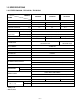
1.3 SPECIFICATIONS 1.3.1 FOR SV08A10A / SV10A10A / SV12A10A MODELS ITEMS SV08A10A SV10A10A SV12A10A 1Ø115V, 60Hz POWER SUPPLY 8,000 10,000 12,000 (W) 840 1,050 1,260 (A) (BTU/W.h) 7.7 9.6 11.5 COOLING CAPACITY (Btu/h) INPUT RUNNING CURRENT E.E.R OPERATING INDOOR (°C) CONDITION OUTDOOR (°C) REFRIGERANT (R-22) CHARGE 9.5 460g(16.2 oz) CONDENSER 19.4(WB)** 35(DB)* 23.9(WB)** 520g(18.3 oz) 2 ROW 16 STACKS, SLIT FIN TYPE EVAPORATOR 26.7(DB)* 615g(21.
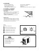
1.4 FEATURES • Built-in adjustable THERMOSTAT • Washable one-touch filter • Compact size • Reliable and efficient rotary compressor is equipped. • Designed for COOLING ONLY. • Powerful and whispering cooling. • Simple installation and service. • Low air-intake, top cooled-air discharge. 1.5 CONTROL LOCATIONS 1.5.1 COOLING ONLY MODEL • VENTILATION The ventilation lever must be in the CLOSE position in order to maintain the best cooling conditions.
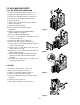
2. DISASSEMBLY INSTRUCTIONS — Before the following disassembly, set POWER SWITCH to OFF and disconnect the power cord. 2.1 MECHANICAL PARTS 2.1.1 FRONT GRILLE 1. Open the inlet grille downward and remove the air filter. 2. Remove the screws which fasten the front grille.(See Figure 1) 3. Pull the front grille from the right side. 4. Remove the front grille.(There are 4 hooks.) 5. Re-install the components by referring to the removal procedure, above.
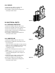
2.2 AIR HANDLING PARTS 2.2.1 AIR GUIDE AND TURBO FAN 1. Remove the front grille. (Refer to section 2.1.1) 2. Remove the cabinet. (Refer to section 2.1.2) 3. Remove the control box. (Refer to section 2.1.3) 4. Remove the 4 screws which fasten the brace. 5. Remove the brace. 6. Remove the 2 screws which fasten the upper air guide. (See Figure 4) 7. Remove the upper air guide. 8. Remove the 2 screws which fasten the evaporator. 9. Move the evaporator forward while pulling it upward slightly. (See Figure 5) 10.
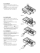
2.2.3 SHROUD 1. Remove the fan. (Refer to section 2.2.2) 2. Remove the shroud. (See Figure 8) 3. Re-install the components by referring to the removal procedure, above. Figure 8 2.3 ELECTRICAL PARTS 2.3.1 OVERLOAD PROTECTOR 1. Remove the cabinet. (Refer to section 2.1.2) 2. Remove the nut which fastens the terminal cover. 3. Remove the terminal cover. (See Figure 9) 4. Remove all the leads from the overload protector. 5. Remove the overload protector. 6.
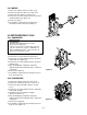
2.3.3 CAPACITOR 1. Remove the cabinet. (Refer to section 2.1.2) 2. Remove the screw and the clamp which fasten the capacitor. 3. Disconnect all the leads of capacitor terminals. 4. Re-install the components by referring to the removal procedure, above. (See Figure 11) Te m pe ra tu re W ar Med Fan m er Co ole Off Hig Co h ol r Lo w Fan Lo w Co ol Med Co ol Mo de Figure 11 2.3.4 POWER CORD 1. Remove the cabinet. (Refer to section 2.1.2) 2.
2.3.7 MOTOR 1. Remove the cabinet. (Refer to section 2.1.2) 2. Remove the turbo fan. (Refer to section 2.2.1) 3. Remove the fan. (Refer to section 2.2.2) 4. Remove the 4 screws which fasten the motor from the Motor Mount. (See Figure 15) 5. Remove the motor. 6. Re-install the components by referring to the removal procedure, above.(See Figure 15) 2.4 REFRIGERATING CYCLE Figure 15 2.4.1 CONDENSER CAUTION Discharge the refrigerant system using a FreonTM Recovery System.
2.4.3 CAPILLARY TUBE 3. Remove the capillary tube. 4. Re-install the components by referring to notes on page 11. 1. Remove the cabinet. (Refer to section 2.1.2) 2. After discharging the refrigerant completely, unbraze the interconnecting tube at the capillary tube. (see caution on previous page) NOTES — Replacement of the refrigerant. 1. When replacing the refrigerant, be sure to Discharge the refrigerant system using a FreonTM recovery System.
Equipment needed: Vacuum pump, Charging cylinder, Manifold gauge, Brazing equipment. Pinch-off tool capable of making a vapor-proof seal, Leak detector, Tubing cutter, Hand Tools to remove components, Service valve.
3. INSTALLATION Awning 3.1 HOW TO INSTALL THE UNIT 1. To avoid vibration and noise, make sure the unit is installed securely and firmly. 2. Install the unit where the sunlight does not shine directly on the unit. If the unit receives direct sunlight, build an awning to shade the cabinet. 3. There should be no obstacle, like a fence, within 20" which might restrict heat radiation from the condenser. 4. To prevent reducing performance, install the unit so that louvers of the cabinet are not blocked. 5.
3.4 WINDOW REQUIREMENTS 1. These instructions are for a horizontal sliding or a casement window. 2. The electrical outlet must be within reach of the power cord. For installation in a casement window, the window frame assembly and the side of the building must be adequate to support the weight of the air conditioner. 21 1/2" min. 21"1 min. 40 /2" max. 15 1/2" min. 16 1/2" max. 15 1/2" min. Horizontal sliding window Casement window 3.
3.6 HORIZONTAL SLIDING WINDOW INSTALLATION Bolt 1. Loosely attach the support bracket to the bottom of bracket using bolts, washers, and nuts. Attach the leveling bolt and nut. (See Figure 22) Bracket Washer Nut Leveling Bolt & Nut Support Bracket Figure 22 2. Remove protective backing from window track seal and apply seal to window track. (See Figure 23) Window jamb Window Type ype C screw scre 11 8 /16" 3. Measure and lightly mark a line 8-1/4" from window jamb.
8. Slide curtain into curtain frame. Slide curtain frame assembly into side guides of the air conditioner cabinet. Make sure curtain is firmly enclosed on all sides by the frame. (See Figure 27) Curtain Frame Figure 27 Curtain 9. Cut side guide seal into 2 equal lengths. Remove protective backing and apply it to the rear side of cabinet side guides, starting just below curtain frame assembly. Pinch off excess length so seal is even with the bottom of side guide. (See Figure 28) 10.
4. TROUBLESHOOTING GUIDE 4.1 OUTSIDE DIMENSIONS Unit: mm(inchs) 368(14 1/2) 521(20 1/2) 607(23 3/5) 4.2 PIPING SYSTEM CONDENSER COIL FAN CAPILLARY TUBE MOTOR COMPRESSOR TURBO FAN EVAPORATOR COIL Following is a brief description of the important components and their functions in the refrigeration system. Refer to Fig. 31 to follow the refrigeration cycle and the flow of the refrigerant in the cooling cycle.
4.3 TROUBLESHOOTING GUIDE In general, possible trouble is classified in two kinds. The one is called Starting Failure which is caused from an electrical defect, and the other is ineffective Air Conditioning caused by a defect in the refrigeration circuit and/or improper application. Unit runs but poor cooling. Ineffective Cooling Check cold air circulation for smooth flow. Dirty indoor coil (Heat exchanger) Check outdoor coil (heat exchanger) & the fan operation. Check heat load increase.
Fails to Start Check power source. Check circuit breaker and fuse. Check control switch setting. Gas leakage of feeler bulb of thermostat Check control switch. Compressor only fails to start. Fan only fails to start. Improper wiring. Drop of power voltage. Improper thermostat setting. Defective of fan motor capacitor. Defective of compressor capacitor. Loose terminal connection. Capacitor check. Irregular motor resistance ( ). Irregular motor insulation ( ). Improper wiring.
ROOM AIR CONDITIONER VOLTAGE LIMITS NAME PLATE RATING MINIMUM MAXIMUM 115V ±10% 103.5V 126.5V COMPLAINT Fan motor will not run CAUSE REMEDY No power Check voltage at outlet. Correct if none. Power supply cord Check voltage to rotary switch. If none, check power supply cord. Replace cord if circuit is open. Rotary switch Check switch continuity. Refer to wiring diagram for terminal identification. Replace switch if defective. Wire disconnected or connection loose Connect wire.
COMPLAINT Compressor will not run, but fan motor runs. Compressor cycles on overload. Compressor cycles on overload. Compressor cycles on overload. Insufficient cooling or heating Excessive noise CAUSE REMEDY Thermostat Check the position of knob If not at the coldest setting, advance the knob to this setting and restart unit. Check continuity of the thermostat. Replace thermostat if circuit is open. Capacitor (Discharge capacitor before servicing.) Check the capacitor.
5. SCHEMATIC DIAGRAM 5.1 CIRCUIT DIAGRAM ■ MODEL : SV10A10A / SV1210A S: Service Parts N: Non Service Parts PART NO. LOCATION NO.
5.2 CIRCUIT DIAGRAM ■ MODEL : SV08A10A S: Service Parts N: Non Service Parts LOCATION NO. PART NO.
6.
7. REPLACEMENT PARTS LIST ■ MODEL : SV08A10A, SV10A10A, SV12A10A P/No LOCATION No.
MEMO —25—
MEMO —26—
Use Factory Certified Parts... FRIEDRICH AIR CONDITIONING CO. Visit our web site at www.friedrich.com Post Office Box 1540 • 4200 N. Pan Am Expressway • San Antonio, Texas 78295-1540 • (210) 357-4400 • FAX (210) 357-4480 P/NO.: 3828A20190X Printed in the U.S.