
Manual


Appendix A (Continued)
.
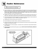
Install the front panel by placing the top of the panel
onto the brackets at the top of the chassis. Rotate
the bottom into place while locating the service
cord (or conduit) in the notch at the bottom or sides
of the front panel.
®
g.
Secure the panel to the chassis with two #10 x
3/4" screws (provided). Attach the bottom return
air louver to the front panel. The louver snaps into
place. The louver can be secured in place with
two #10 x 3/4" screws provided (optional).
®
Louver Screw /_
Front Panel
Screw
NOTE: If the unit is mounted flush to the floor, the service cord
MUST be rerouted through the side of the front panel closest to
the receptacle. A notch MUST be made in the front panel side
where the cord exits the unit. It is the responsibility of the installer
to create an exit notch. See the diagram for suggested opening
size and placement.
@
Not to scale
10. For 230/208 volt units, plug the cord (if applicable) intoan appropriate receptacle. For 265 volt units see Appendix
C on page 17.The extra cord may be coiled inside the front panel behind the return air louver. Restore power to the
unit.
rl