
Manual


Appendix A (Continued)
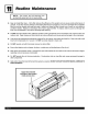
Remote Thermostat 208V Operation
CONNECTION DIAGRAM
CAUTION
If the supply voltage is 208V, the low volt-
age transformer IVlUST be wired for 208V
operation. Failure to do so will result in lower
control voltages to the unit and can dam-
age low voltage components.
The simplified connection diagram at left shows the
factory configured wiring set for 240V operation. If
you are going to use 208V exclusively, switch the
two (2) black wires on the 240V post of the primary
side of the transformer to the 208V post. This will
ensure correct secondary (low) voltages for the unit.
This is only required on the remote thermostat units.
Remote Thermostat Unit Operation
These units are controlled by the use of a remote ther-
mostat that will cycle the unit to maintain desired room
temperature. See thermostat operating manual for de-
tails.
The fan speed switch on the control panel is indepen-
dent of the thermostat and controls the fan speed. If you
wish high speed fan operation, set switch to high. For low
Control
Fan Speed
Switch Operation
Operation
Selects high speed or low speed
mi,;,-i-ii i