Uni- Fit R Thru-the-Wall Series Service and Parts Manual Thru-the-Wall Series 115 Volts US08C10 US10C10 US12C10 230 Volts US10C30 US12C30 US14C30 Unifit Cool Svc Parts 2010 (05/10) Unifit.
CONTENTS 2.4 REFRIGERATION CYCLE.................................14 2.4.1 CONDENSER ......................................14 2.4.2 EVAPORATOR ....................................14 2.4.3 CAPILLARY TUBE...............................14 1. PREFACE 1.1 SAFETY PRECAUTIONS ...............................2 1.2 INSULATION RESISTANCE TEST.................2 1.3 SPECIFICATIONS ..........................................3~8 1.4 FEATURES .....................................................9 1.5 CONTROL LOCATIONS .....
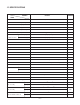
1.3 SPECIFICATIONS MODELS US08C10 ITEMS POWER SUPPLY REMARK 1Ø, 115V, 60Hz COOLING CAPACITY (Btu/h) INPUT 8,000 (W) 830 RUNNING CURRENT (A) 7.5 E.E.R 9.6 (Btu/w.h) REFRIGERANT (R410A) CHARGE 400g(14.
1.3 SPECIFICATIONS MODELS US10C10 ITEMS POWER SUPPLY REMARK 1Ø, 115V, 60Hz COOLING CAPACITY (Btu/h) INPUT 9,800 (W) 1,040 RUNNING CURRENT (A) 9.6 E.E.R 9.4 (Btu/w.h) REFRIGERANT (R-410A) CHARGE 445g(15.7OZ) OPERATING INDOOR (°F) 80 (DB) 67(WB) TEMPERATURE OUTDOOR (°F) 95(DB) 75 (WB) EVAPORATOR 2 ROW 12STACKS Ø5 .
MODELS US10C30 ITEMS REMARK 1Ø, 230V/208V, 60Hz POWER SUPPLY 10,000/9,800 COOLING CAPACITY (Btu/h) INPUT (W) 1060/1040 RUNNING CURRENT (A) 4.7/5.2 E.E.R 9.4/9.4 (Btu/w.h) REFRIGERANT (R410A) CHARGE 460g(16.2 OZ) OPERATING INDOOR (°F) 80(DB) 67(WB) TEMPERATURE OUTDOOR (°F) 95(DB) 75(WB) 2 ROW 12STACKS EVAPORATOR Ø 5.
MODELS US12C10 ITEMS POWER SUPPLY 1Ø, 230V/208V, 60Hz COOLING CAPACITY (Btu/h) 11500/11200 INPUT (W) REMARK 1220/1190 RUNNING CURRENT (A) 5.6/6.0 E.E.R 9.4/9.4 (Btu/w.h) REFRIGERANT (R-410A) CHARGE 525g(18.
MODELS US12C30 ITEMS POWER SUPPLY REMARK 1Ø, 230/208V, 60Hz COOLING CAPACITY (Btu/h) INPUT 11,500/11,200 (W) 1,220/1,190 RUNNING CURRENT (A) 5.6/6.0 E.E.R 9.4/9.4 (Btu/w.h) 510g(18.
MODELS US14C30 ITEMS POWER SUPPLY 1Ø, 230/208V, 60Hz COOLING CAPACITY (Btu/h) 13,000/12,600 INPUT (W) REMARK 1,530/1,480 RUNNING CURRENT (A) 7.0/7.5 E.E.R 8.5/8.5 (Btu/w.h) 510g(18.
1.4 FEATURES • Designed for cooling only. • Built in adjustable THERMOSTAT. • Powerful and quiet. • Slide out chassis for the simple installation and service. • Washable one-touch filter. • Compact size. 1.5 CONTROL LOCATIONS 1.5.1 COOLING ONLY MODEL • OPERATION • VENTILATION Push the lever to the "CLOSE" position to cool, heat or recirculate room air only. Pull the lever to the "OPEN" position to exhaust smoke or stale air from the room.
2. DISASSEMBLY INSTRUCTIONS — Prior to disassembling the unit, make sure that the POWER is off and the power cord is unplugged from the wall receptacle. 2.1 MECHANICAL PARTS 2.1.1 FRONT GRILLE 1. Open the inlet grille downward. 2. Remove the screw which fastens the front grille. 3. Pull the front grille from the right side. 4. Remove the front grille. (See Fig. 1) 5. Re-install the component by referring to the removal procedure. Figure 1 2.1.2 CABINET 1.
2.2 AIR HANDLING PARTS 2.2.1 ORIFICE, AND TURBO FAN 1. Remove the front grille. (Refer to section 2.1.1) 2. Remove the cabinet. (Refer to section 2.1.2) 3. Remove the 2 screws which fasten the evaporator at the left side and the right side. (See Fig. 4) 4. Move the evaporator to the side carefully. Figure 4 5. Remove the orifice. (See Fig. 5) Figure 5 8. Using handheld pliers, remove the clamp which secures the turbo fan. (See Fig. 6) Figure 6 9.
2.2.3 SHROUD 1. Remove the fan. (Refer to section 2.2.2) 2. Remove the shroud. (See Fig. 9) 3. Re-install the components by referring to the removal procedures, above. 2.3 ELECTRICAL PARTS 2.3.1 MOTOR 1. Remove the cabinet. (Refer to section 2.1.2) 2. Remove the clamp cord and disconnect the wire housing in control box. (Refer to section 2.1.3) 3. Remove the turbo fan. (Refer to section 2.2.2) 4. Remove the fan. (Refer to section 2.2.2) 5. Remove the 4 or 2 screws which fasten the motor. (See Fig. 10) 6.
2.3.4 POWER CORD 1. Remove the control box. (Refer to section 2.1.3) 2. Unfold the control box. (Refer to section 2.3.3) 3. Disconnect the grounding screw from the Base pan. 4. Disconnect 2 receptacles. 5. Remove a screw which fastens the clip cord. 6. Pull the power cord. (See Fig. 13) 7. Re-install the components by referring to the removal procedure, above. (Use only one ground-marked hole, , for ground connection.) 8.
2.4 REFRIGERATION CYCLE CAUTION Discharge the refrigerant system using a FreonTM Recovery System. Install a valve for the recovery, before venting the Freon, remove the valve when finished. 2.4.1 CONDENSER 1. Remove the cabinet. (Refer to section 2.1.2) 2. Remove the brace. (Refer to section 2.2.1) 3. Remove the 7 screws which fasten the condenser. 4. After discharging the refrigerant completely into a FreonTM Recovery System, unbraze the interconnecting tube at the condenser connections. 5.
NOTES — Replacement of the refrigeration cycle. 1. When replacing refrigeration components, be sure to discharge the refrigerant system using a FreonTM recovery System. Install a valve for the recovery, before venting the Freon, remove the valve when finished. 2. After discharging the unit completely, remove the desired component, and unbraze the pinch-off tubes. 3. Solder service valves into the pinch-off tube ports, leaving the valves open. 4. Solder the pinch-off tubes with Service valves. 5.
Equipment needed: Vacuum pump, Charging cylinder, Manifold gauge, Brazing equipment, Pinch-off tool capable of making a vapor-proof seal, Leak detector, Tubing cutter, Hand Tools to remove components, Service valve.
3. TROUBLESHOOTING GUIDE 3.1 OUTSIDE DIMENSIONS 20-3/32" (499mm) 14-3/8" (366mm) 24" (610mm) 3.2 PIPING SYSTEM CONDENSER COILS FAN CAPILLARY TUBE MOTOR COMPRESSOR TURBO FAN EVAPORATOR COILS : REFRIGERANT FLOW Following is a brief description of the important components and their functions in the refrigeration system. Refer to Fig. 18 to follow the refrigeration cycle and the flow of the refrigerant in the cooling cycle.
3.3 TROUBLESHOOTING GUIDE In general, possible trouble is classified in two causes. One is called Starting Failure which is caused from an electrical defect, and the other is Ineffective Air Conditioning caused by a defect in the refrigeration circuit and/or improper application. Unit is running but cooling is ineffective Ineffective Cooling Check cold air circulation for smooth flow. Check outdoor coil (heat exchanger) & the fan operation. Dirty indoor coil (Heat exchanger) Check gas leakage.
Fails to Start Check power source. Check circuit breaker and fuse. Check control switch setting. Check control board Only compressor fails to start. Only fan fails to start. Improper wiring. Drop in power voltage. Improper thermostat setting Defect of fan motor capacitor. Defective compressor capacitor. Loose terminal connection. Check capacitor. Irregular motor resistance ( ). Irregular motor insulation ( ). Improper wiring Replacement.
COMPLAINT Fan motor will not run. CAUSE REMEDY No power Check voltage at outlet. Correct if none. Wire disconnected or connection loose Connect wire. Refer to wiring diagram for terminal identification. Repair or replace loose terminal. Capacitor (Discharge capacitor before testing.) Test capacitor. Replace if not within ±10% of manufacturer's rating. Replace if shorted, open, or damaged. Will not rotate Fan blade hitting shroud or blower wheel hitting scroll. Realign assembly.
COMPLAINT Compressor will not run, but fan motor runs. CAUSE REMEDY Voltage Check voltage. See the limits on the preceding. page. If not within limits, call an electrician. Wiring Check the wire connections, if loose, repair or replace the terminal. If wires are off, refer to wiring diagram for identification, and replace. Check wire locations. If not per wiring diagram, correct. Capacitor (Discharge capacitor before servicing.) Check the capacitor.
COMPLAINT Compressor cycles on overload. Insufficient cooling or heating Excessive noise. REMEDY CAUSE Voltage Check the voltage. See the limits on the preceding page. If not within limits, call an electrician. Overload Check overload, if externally mounted. Replace if open. (If the compressor temperature is high, remove the overload, cool, and retest.) Fan motor If not running, determine the cause. Replace if required. Condenser air flow restriction Remove the cabinet.
4. SCHEMATIC DIAGRAM 4.1 CIRCUIT DIAGRAM WIRING DIAGRAM (SMPS) 250V/T2A (250V/T3.
Exploded View Exploded View C 152302 147581 132100 147582-1 135303 147582-2 131400 149980 135312 359012 W48602 559011 346811 349480 435300 352380 435301 731273 267110 130410 A 264110 268711-2 249950 B 567480 567502 268711-1 Co ol En e Savrg y er Fa n MO DE Ti m F1 F2 LOW F3 MED HIG H er TE TIM ER W0CZZ 'F MP F SP A N EE D PO WE R 238310 550140 237200 —24—
LocNo Description US08C10 W0CZZ CAPACITOR,FILM,BOX 67300709 130410 BASE ASSEMBLY,SINGLE 67302925 130900 CABINET 67303717 132100 FRAME 67308102 135303 GRILLE,INLET 67306106 135312 GRILLE ASSEMBLY,FRONT(SINGLE) 67306012 238310 ESCUTCHEON 67500114 W48602 CLAMP,SPRING 67302500 346811 MOTOR ASSEMBLY,SINGLE 67303021 147581 LOUVER,HORIZONTAL 67306205 147582-1 LOUVER,VERTICAL 67306256 147582-2 LOUVER,VERTICAL 67306257 149980 SHROUD 67500112 550140 DAMPER,COMPRESSOR 673050
LocNo Description US10C10 W0CZZ CAPACITOR,FILM,BOX 67300724 130410 BASE ASSEMBLY,SINGLE 67305520 130900 CABINET 67303717 132100 FRAME 67308102 135303 GRILLE,INLET 67306106 135312 GRILLE ASSEMBLY,FRONT(SINGLE) 67306012 238310 ESCUTCHEON 67500114 W48602 CLAMP,SPRING 67302500 346811 MOTOR ASSEMBLY,SINGLE 67303023 147581 LOUVER,HORIZONTAL 67306205 147582-1 LOUVER,VERTICAL 67306256 147582-2 LOUVER,VERTICAL 67306257 349600 BRACKET,MOTOR 67303606 149980 SHROUD 67500112
LocNo Description US10C30 W0CZZ CAPACITOR,FILM,BOX 67300709 130410 BASE ASSEMBLY,SINGLE 67302925 130900 CABINET 67303717 132100 FRAME 67308102 135303 GRILLE,INLET 67306106 135312 GRILLE ASSEMBLY,FRONT(SINGLE) 67306012 238310 ESCUTCHEON 67500114 W48602 CLAMP,SPRING 67302500 346811 MOTOR ASSEMBLY,SINGLE 67303024 147581 LOUVER,HORIZONTAL 67306205 147582-1 LOUVER,VERTICAL 67306256 147582-2 LOUVER,VERTICAL 67306257 149980 SHROUD 67500112 550140 DAMPER,COMPRESSOR 673050
LocNo Description US12C10 W0CZZ CAPACITOR,FILM,BOX 67300729 130410 BASE ASSEMBLY,SINGLE 67305520 130900 CABINET 67303717 132100 FRAME 67308102 135303 GRILLE,INLET 67306106 135312 GRILLE ASSEMBLY,FRONT(SINGLE) 67306012 238310 ESCUTCHEON 67500114 W48602 CLAMP,SPRING 67302500 346811 MOTOR ASSEMBLY,SINGLE 67303023 147581 LOUVER,HORIZONTAL 67306205 147582-1 LOUVER,VERTICAL 67306256 147582-2 LOUVER,VERTICAL 67306257 349600 BRACKET,MOTOR 67303606 149980 SHROUD 67500112
LocNo· Description US12C30 W0CZZ CAPACITOR,FILM,BOX 67300726 130410 BASE ASSEMBLY,SINGLE 67305520 130900 CABINET 67303717 132100 FRAME 67308102 135303 GRILLE,INLET 67306106 135312 GRILLE ASSEMBLY,FRONT(SINGLE) 67306012 238310 ESCUTCHEON 67500114 W48602 CLAMP,SPRING 67302500 346811 MOTOR ASSEMBLY,SINGLE 67303037 147581 LOUVER,HORIZONTAL 67306205 147582-1 LOUVER,VERTICAL 67306256 147582-2 LOUVER,VERTICAL 67306257 349600 BRACKET,MOTOR 67303606 149980 SHROUD 67500112
LocNo· Description US14C30 W0CZZ CAPACITOR,FILM,BOX 67300709 130410 BASE ASSEMBLY,SINGLE 67302926 130900 CABINET 67303717 132100 FRAME 67308102 135303 GRILLE,INLET 67306106 135312 GRILLE ASSEMBLY,FRONT(SINGLE) 67306012 238310 ESCUTCHEON 67500114 W48602 CLAMP,SPRING 67302500 346811 MOTOR ASSEMBLY,SINGLE 67303037 147581 LOUVER,HORIZONTAL 67306205 147582-1 LOUVER,VERTICAL 67306256 147582-2 LOUVER,VERTICAL 67306257 349600 BRACKET,MOTOR 67303606 149980 SHROUD 67500112
FRIEDRICH AIR CONDITIONING CO. Visit our web site at www.friedrich.com Post Office Box 1540 • 4200 N. Pan Am Expressway • San Antonio, Texas 78295-1540 • (210) 357-4400 • FAX (210) 357-4480 P/NO.:3828A20294U Printed in the U.S.