
Service and Parts Manual (2016, 2017, 2018, 2014, 2015, 2013, 2012)

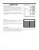

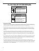
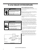
Table Of Contents
- INTRODUCTION
- IMPORTANT SAFETY INFORMATION
- PERSONAL INJURY OR DEATH HAZARDS
- Operation of Equipment in During Construction
- Equipment Identification
- Model and Serial Number Location
- Model and Serial Number information is found on the Manufacturer’s DATA TAG, located on the front or top.
- Model Number Reference Guide
- SERIAL NUMBER REFERENCE GUIDE
- Chassis Specifications
- Small Chassis Dimensions
- Large Chassis Dimensions
- Electrical Data
- Electrical Requirements
- Electrical Ratings Table
- Supply Air Flow and Data
- ELECTRONIC CONTROL BOARD FEATURES
- Electronic Sequence of Operation
- Interface Connector Definitions
- Remote Wall Thermostat
- Remote Wall Thermostat Location
- Desk Control
- Auxiliary Fan Control
- Unit Heat Control Operation - Heat Pump With Electric Heat
- Refrigeration Sequence Of Operation
- Remove The Chassis
- Servicing / Chassis Quick Changeouts
- To Remove the Chassis from the Closet:
- Refrigerant Charging
- Undercharged Refrigerant Systems
- Overcharged Refrigerant Systems
- Restricted Refrigerant System
- Sealed System Method of Charging/ Repairs
- Checking External Static Pressure
- Explanation of charts
- Indoor Airflow Data
- Ductwork Preparation
- Fresh Air Door
- Checking Approximate Airflow
- Electric Heat Strips
- COMPONENT TESTING
- Hermetic Components Check
- Reversing Valve Description And Operation
- Testing The Reversing Valve Solenoid Coil
- Checking The Reversing Valve
- Touch Test Chart : To Service Reversing Valves
- Compressor Checks
- Compressor Replacement -Special Procedure in Case of Compressor Burnout
- Fan Motor
- Capacitors
- Heating Element and Limit Switch
- Drain Pan Valve
- Thermistor Resistence Values (This Table Applies to All Thermistors)
- Testing the Diagnostic Service Module
- Testing the Electronic Control Board
- ELECTRONIC CONTROL BOARD COMPONENTS IDENTIFICATION AND TESTING
- Error Codes and Alarm Status
- Electrical Troubleshooting Chart - Cooling
- 9K Btu, 12K Btu, & 18K Btu
- 24K Btu
- Electrical Troubleshooting Chart - Heat Pump
- Troubleshooting Chart - Cooling
- 9-18K VEA 208/230V
- 9-18K VHA 208/230V
- 9-18K VHA 265V
- 24K VEA 208/230V 2.5/3.4/5.0
- 24K VEA 208/230V 7.5/10.0
- 24K VHA 208/230V 2.5/3.4/5.0
- 24K VHA 208/230V 7.5/10
- 24K VHA 265V 2.5/3.4/5.0
- 24K VHA 265V 7.5/10.0
- VEA9K, VHA9K, VEA12K, VHA12K, VEA18K Figure 901
- AVAILABLE ACCESSORIES
- Thermostat - Rt6
- Thermostat - Rt6p
- Thermostat - WRT1
- Drain Pan

23 PB
OPERATION
Remote Wall Thermostat Location
The thermostat should not be mounted where it may be affected by drafts,
discharge air from registers (hot or cold), or heat radiated from the sun
appliances, windows etc.. The thermostat should be located about 5 Ft. above
the oor in an area of average temperature, with good air circulation.
Mercury bulb type thermostats MUST be level to control temperature
accurately to the desired set-point. Electronic digital type thermostats should
be level for aesthetics.
Note: An improperly operating or poorly located remote wall thermostat
can be the source of perceived equipment problems. A careful check of the
thermostat’s location and wiring must be made then to ensure that it is not the
source of problems.
Desk Control
The unit’s electronic control has built-in provisions for connection to an exter-
nal switch to control power to the unit. The switch can be a central desk control
system or even a normally open door switch.
For desk control operation, connect one side of the switch to the D1 terminal and the
other to the D2 terminal (See page 12). Whenever the switch closes, the unit operation
will stop.
Maximum wire Length for Desk Control
Switch
Wire Size Maximum Length
#24 400 ft.
#22 600 ft.
#20 900 ft.
#18 1500 ft.
#16 2000 ft.
Auxiliary Fan Control
The electronic control also has the ability to control a 24 VAC relay to activate an auxiliary, or transfer fan. The outputs are
listed as F1 and F2 on the interface connector (See gure 302).
To connect the relay, simply wire one side of the relay to F1 and the other side to F2. Anytime that the fan runs, the terminals
will send a 24 VAC signal to the relay. The relay must be 24 VAC, 50mA or less.
Note: The Desk Control, Auxiliary Fan relay and wires must be eld supplied.
Figure 303 (Thermostat Locations)