
Service and Parts Manual (2016, 2017, 2018, 2014, 2015, 2013, 2012)


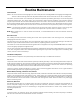
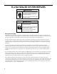
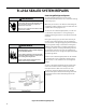
Table Of Contents
- INTRODUCTION
- IMPORTANT SAFETY INFORMATION
- PERSONAL INJURY OR DEATH HAZARDS
- Operation of Equipment in During Construction
- Equipment Identification
- Model and Serial Number Location
- Model and Serial Number information is found on the Manufacturer’s DATA TAG, located on the front or top.
- Model Number Reference Guide
- SERIAL NUMBER REFERENCE GUIDE
- Chassis Specifications
- Small Chassis Dimensions
- Large Chassis Dimensions
- Electrical Data
- Electrical Requirements
- Electrical Ratings Table
- Supply Air Flow and Data
- ELECTRONIC CONTROL BOARD FEATURES
- Electronic Sequence of Operation
- Interface Connector Definitions
- Remote Wall Thermostat
- Remote Wall Thermostat Location
- Desk Control
- Auxiliary Fan Control
- Unit Heat Control Operation - Heat Pump With Electric Heat
- Refrigeration Sequence Of Operation
- Remove The Chassis
- Servicing / Chassis Quick Changeouts
- To Remove the Chassis from the Closet:
- Refrigerant Charging
- Undercharged Refrigerant Systems
- Overcharged Refrigerant Systems
- Restricted Refrigerant System
- Sealed System Method of Charging/ Repairs
- Checking External Static Pressure
- Explanation of charts
- Indoor Airflow Data
- Ductwork Preparation
- Fresh Air Door
- Checking Approximate Airflow
- Electric Heat Strips
- COMPONENT TESTING
- Hermetic Components Check
- Reversing Valve Description And Operation
- Testing The Reversing Valve Solenoid Coil
- Checking The Reversing Valve
- Touch Test Chart : To Service Reversing Valves
- Compressor Checks
- Compressor Replacement -Special Procedure in Case of Compressor Burnout
- Fan Motor
- Capacitors
- Heating Element and Limit Switch
- Drain Pan Valve
- Thermistor Resistence Values (This Table Applies to All Thermistors)
- Testing the Diagnostic Service Module
- Testing the Electronic Control Board
- ELECTRONIC CONTROL BOARD COMPONENTS IDENTIFICATION AND TESTING
- Error Codes and Alarm Status
- Electrical Troubleshooting Chart - Cooling
- 9K Btu, 12K Btu, & 18K Btu
- 24K Btu
- Electrical Troubleshooting Chart - Heat Pump
- Troubleshooting Chart - Cooling
- 9-18K VEA 208/230V
- 9-18K VHA 208/230V
- 9-18K VHA 265V
- 24K VEA 208/230V 2.5/3.4/5.0
- 24K VEA 208/230V 7.5/10.0
- 24K VHA 208/230V 2.5/3.4/5.0
- 24K VHA 208/230V 7.5/10
- 24K VHA 265V 2.5/3.4/5.0
- 24K VHA 265V 7.5/10.0
- VEA9K, VHA9K, VEA12K, VHA12K, VEA18K Figure 901
- AVAILABLE ACCESSORIES
- Thermostat - Rt6
- Thermostat - Rt6p
- Thermostat - WRT1
- Drain Pan

30 PB
R-410A SEALED SYSTEM REPAIRS
WARNING
RISK OF ELECTRIC SHOCK
Unplug and/or disconnect all electrical power
to the unit before performing inspections,
maintenances or service.
Failure to do so could result in electric shock,
serious injury or death.
WARNING
HIGH PRESSURE HAZARD
Sealed Refrigeration System contains refrigerant
and oil under high pressure.
Proper safety procedures must be followed,
and proper protective clothing must be worn
when working with refrigerants.
Failure to follow these procedures could
result in serious injury or death.
Undercharged Refrigerant Systems
An undercharged system will result in poor
performance (low pressures, etc.) in both the heating
and cooling cycle.
Whenever you service a unit with an undercharge of
refrigerant, always suspect a leak. The leak must be
repaired before charging the unit.
To check for an undercharged system, turn the unit
on, allow the compressor to run long enough to
establish working pressures in the system (15 to 20
minutes).
During the cooling cycle you can listen carefully at
the exit of the metering device into the evaporator;
an intermittent hissing and gurgling sound indicates
a low refrigerant charge. Intermittent frosting and
thawing of the evaporator is another indication of a
low charge, however, frosting and thawing can also
be caused by insufcient air over the evaporator or
partial restriction in the refrigeration system besides
the metering device..
Checks for an undercharged system can be made at
the compressor. If the compressor seems quieter
than normal, it is an indication of a low refrigerant
charge.
A check of the amperage drawn by the compressor
motor should show a lower reading. (Check the
Unit Specication.) After the unit has run 10 to
15 minutes, check the gauge pressures. Gauges
connected to system with an undercharge will have
low head pressures and substantially low suction
pressures.
Figure 601 (Undercharged System)