Service/ Parts Manual VERT-I-PAK Standard Chassis Models VHA - 09K25RTP, 09K34RTP, 09K50RTP VHA - 09R25RTP, 09R34RTP, 09R50RTP 9K 12K VHA - 12K25RTP, 12K34RTP, 12K50RTP VHA - 12R25RTP, 12R34RTP, 12R50RTP 18K VHA - 18K25RTP, 18K34RTP, 18K50RTP, 18K75RTP VHA - 18R25RTP, 18R34RTP, 18R50RTP, 18K75RTP 24K VHA - 24K25RTP, 24K34RTP, 24K50RTP, 24K75RTP, 24K10RTP VHA - 24R25RTP, 24R34RTP, 24R50RTP, 24R75RTP, 24R10RTP 1 95992012_03
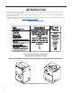
Table of Contents INTRODUCTION Important Safety Information Personal Injury Or Death Hazards Operation of Equipment in During Construction Equipment Identification Model and Serial Number Location Model and Serial Number information is found on the Manufacturer’s DATA TAG, located on the front or top.
Fan Motor 49 Capacitors 49 Heating Element and Limit Switch 50 Heater Elements And Limit Switches’ Specifications 50 Drain Pan Valve 52 Thermistor Resistence Values (This Table Applies to All Thermistors) 53 Testing the Diagnostic Service Module 54 Testing the Electronic Control Board 54 Electronic Control Board Components Identification And Testing 55 24k Indoor Blower Motor 56 TROUBLESHOOTING 57 Error Codes and Alarm Status 57 Electrical Troubleshooting Chart - Cooling 59 9K Btu, 12K Btu, & 18
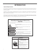
INTRODUCTION Important Safety Information The information in this manual is intended for use by a qualified technician who is familiar with the safety procedures required for installation and repair, and who is equipped with the proper tools and test instruments required to service this product.
Personal Injury Or Death Hazards INTRODUCTION WARNING SAFETY FIRST Do not remove, disable or bypass this unit’s safety devices. Doing so may cause fire, injuries, or death. AVERTISSEMENT Ne pas supprime, désactiver ou contourner cette l´unité des dispositifs de sécurité, faire vous risqueriez de provoquer le feu, les blessures ou la mort. ADVERTENCIA No eliminar, desactivar o pasar por alto los dispositivos de seguridad de la unidad. Si lo hace podría producirse fuego, lesiones o muerte.
INTRODUCTION Personal Injury Or Death Hazards 6 • REFRIGERATION SYSTEM REPAIR HAZARDS: • Use approved standard refrigerant recovering procedures and equipment to relieve high pressure before opening system for repair. • Do not allow liquid refrigerant to contact skin. Direct contact with liquid refrigerant can result in minor to moderate injury. • Be extremely careful when using an oxy-acetylene torch. Direct contact with the torch’s flame or hot surfaces can cause serious burns.
INTRODUCTION Operation of Equipment in During Construction • OPERATION OF EQUIPMENT MUST BE AVOIDED DURING CONSTRUCTION PHASES WHICH WILL PRODUCE AIRBORNE DUST OR CONTAMINTES NEAR OR AROUND AIR INTAKE OPENINGS: • Wood or metal framing; • Drywalling or sheathing, • Spackling or applying joint compound. • Sanding or grinding. • Moulding or trimwork.
INTRODUCTION This service manual is designed to be used in conjunction with the installation and operation manuals provided with each air conditioning system. This service manual was written to assist the professional service technician to quickly and accurately diagnose and repair malfunctions. Installation procedures are not given in this manual. They are given in the Installation and Operation Manual which can be aquired on the Friedrich website (www.friedrich.com).
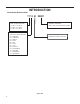
Model Number Reference Guide INTRODUCTION V H A 09 K 34 RT P - A SERIES V=VERTICAL SERIES FUNCTION ENGINEERING REVSION LETTER INDICATES AN ENGINEERING MODIFICATION TO AN EXISTING MODEL MARKETING SUFFIX LETTER INDICATES MODIFICATION TO AN EXISTING MODEL SERIES H - HEAT PUMP OPTIONS RT = STANDARD REMOTE OPERATION DESIGN SERIES A = 32”/47” CABINET NOMINAL CAPACITY A SERIES (Btu/h) 09= 9,000 12 = 12,000 18 = 18,000 24 = 24,000 ELECTRIC HEATER SIZE A SERIES 25 = 2.5 KW 75 = 7.5KW 34 = 3.
Serial Number Reference Guide INTRODUCTION 17 12 M 00001 NUMERIC SEQUENCE FIRST UNIT OF EACH MONTH = 00001 YEAR OF MANUFACTURE 17 = 2017 18 = 2018 19 = 2019 20 = 2020 21 = 2021 22 = 2022 MONTH OF MANUFACTURE 01 = JANUARY 02 = FEBRUARY 03 = MARCH 04 = APRIL 05 = MAY 06 = JUNE 07 = JULY 08 = AUGUST 09 = SEPTEMBER 10 = OCTOBER 11 = NOVEMBER 12 = DECEMBER MANUFACTURING LOCATION Figure 104 10
SPECIFICATIONS General Specifications MODEL VHA09K VHA09R VHA12K VHA12R VHA18K VHA18R VHA24K VHA24R TOTAL COOLING CAP. 9300 9300 11500 11500 18400 18400 22500 22500 SENSIBLE COOL CAP. 7440 7440 9085 9085 13430 13430 15750 15750 POWER (W) 845 845 1045 1045 1670 1670 2045 2045 EER 11.0 11.0 11.0 11.0 11.0 11.0 11.0 11.0 HEATER SIZE (KW) 2.5/3.4/ 5.0 2.5/3.4/ 5.0 2.5/3.4/ 5.0 2.5/3.4/ 5.0 2.5/3.4/ 5.0/7.5 2.5/3.4/ 5.0/7.5 2.5/3.4/ 5.0/7.5/ 10.0 2.5/3.4/ 5.
SPECIFICATIONS Chassis Specifications 9K, 12K Front Side 23 1/8” Rear 23 1/8” 10” SUPPLY AIR D UC T DIAMETER 2 15/16” 10 1/8” CONDEN SE R INLET AIR 29 1/2” RETURN AIR 29 1/2” CONDENSER EXHAUST AIR 1 1/2” UNIT TOP VIEW DIMENSIONS O utside Wall Figure 202 (9-12K Chassis Specs) 12 31” 19 1/2”
SPECIFICATIONS 18K Dimensions SUPPLY AIR 10 DUCT DIAMETER ELECTRICAL ENTRY BOTH SIDES 5 1/16 2 3/16 2 1/2 RETURN AIR CONDENSER INLET AIR 39 3/4 42 5/8 47 15/16 31 CONDENSER EXHAUST AIR FRONT SIDE 1 1/2 REAR UNIT TOP VIEW DIMENSIONS 22 5 /16 " control box electrical entrance 8 3 /8 " 6 3 /16 " 4 3 /16 " 5 5 /16 " 7 3 /16" Figure 203 (18K Chassis Specs) 13 11 11/16
SPECIFICATIONS 24K Dimensions SUPPLY AIR 20 5/8 DUCT ELECTRICAL ENTRY BOTH SIDES 6 55/64 DUCT 5 5/32 1 DUCT 15 7/16 2 1/2 RETURN AIR 46 23/32 51 7/8 CONDENSER INLET AIR 44 CONDENSER EXHAUST AIR 31 9/32 1 1/2 FRONT SIDE REAR UNIT TOP VIEW DIMENSIONS 12 19/64 1 1/2 6 55/64 1 1/2 3 55/64 Outside Wall 20 5/8 Figure 204 24K Chassis Specs) 14
SPECIFICATIONS Electrical Data MODEL 9K HEATER WATTS 2050-2500 12K 2780-3400 4090-5000 VOLTAGE 2050-2500 2780-3400 4090-5000 208-230 ELECTRIC HEATING BTU 7000-8500 9500-11600 13900-17000 7000-8500 9500-11600 13900-17000 ELEC. HEATING CURRENT (AMPS) 11.1-12.0 14.6-16.0 20.9-22.9 11.1-12.0 14.6-16.0 20.9-22.9 MINIMUM CIRCUIT AMPACITY 15 20.0 29.2 15 20.0 29.2 BRANCH CIRCUIT FUSE (AMPS) 15 20 30 15 20 30 LRA - COMPRESSOR (AMPS) 21.0 21.0 21.0 23.0 23.0 23.
SPECIFICATIONS Electrical Data MODEL 18K HEATER WATTS 2050-2500 24K 2780-3400 4090-5000 2050-2500 VOLTAGE 2780-3400 4090-5000 6135-7500 818010000 208-230 ELECTIC HEATING BTU 7000-8500 9500-11600 1390017000 7000-8500 9500-11600 1390017000 2090025600 2790034100 ELEC. HEATING CURRENT (AMPS) 11.1-12.0 14.6-16.0 20.9-22.9 11.3-12.3 14.8-16.2 21.1-23.1 30.9-34.0 40.7-44.9 MINIMUM CIRCUIT AMPACITY 15.0 20.0 29.2 15.4 20.3 29.0 42.6 56.
Electrical Requirements SPECIFICATIONS ELECTRICAL REQUIREMENTS WIRE SIZE USE ONLY WIRE SIZE RECOMMENDED FOR SINGLE OUTLET BRANCH CIRCUIT. FUSE/CIRCUIT BREAKER USE ONLY TYPE AND SIZE FUSE OR HACR CIR- CUIT BREAKER INDICATED ON UNIT’S RATING GUIDE. PROPER OVER CURRENT PROTECTION TO THE UNITS IS THE RESPONSIBILITY OF THE OWNER. GROUNDING UNIT MUST BE GROUNDED FROM BRANCH CIRCUIT TO UNIT, OR THROUGH SEPARATE GROUND WIRE PROVIDED ON PERMANENTLY CONNECTED UNITS.
SPECIFICATIONS Sound Data Sound Power and STC MODEL INDOOR (DBA) OUTDOOR (DBA) STC HIGH COOL LOW COOL HIGH COOL LOW COOL VHA09 23 63.6 61.4 75.4 72.9 VHA12 23 63.0 60.8 75.3 72.7 VHA18 24 67.2 65.7 74.9 74.8 VHA24 25 67.8 66.4 78.5 72.
SPECIFICATIONS Supply Air Flow and Data MODEL VHA 09/12 FAN SPEED LOW ESP (“) CFM 0.0” VHA 18 VHA 24 HIGH LOW HIGH LOW HIGH 470 520 730 800 755 805 0.05” 460 510 670 735 700 750 0.10” 430 490 630 675 660 700 0.15” 410 470 595 640 615 665 0.20” 360 440 550 600 575 625 0.25” 310 400 505 550 525 580 0.30” 260 350 455 500 485 540 0.35” -- -- 400 445 450 500 0.
SPECIFICATIONS Required Minimum Clearances Building Exterior Unit Opening Requirements be installed no closer than 12” apart when two units are side by side. If three or more units are to operate next to one with adjacent, outset units, a minimum distance of 64” must be kept between units (Figure C). Also, a vertical clearance of ground.
OPERATION Electronic Control Board Features The Friedrich Vert-I-Pak has state of the art features to improve guest comfort and conserve energy. Below is a list of standard features on every Friedrich VPAK and their benefitt to the owner. Quite Start/ Stop Fan Delay The fan start and stop delays prevent abrupt changes in room acoustics due to the compressor energizing or stopping immediately. Upon call for cooling or heating the unit fan will run for five seconds prior to en-ergizing the compressor.
Operation Electronic Sequence of Operation Compressor and Reversing Valve Control Active Mode Compressor Reversing Valve Cooling On De-Energized Heat - Pump On Energized Heat - Electric Off Fan Only Off Reversing Valve The reversing valve stays in the last state until a call for heat or cooling. The reversing valve only changes when required to provide coooling or heat pump. Leave the reversing valve in it’s last state until it’s required to change.
OPERATION Compressor Lock Out Time The lockout feature ensures that the compressor is de-energized for a period of time. The timer varies randomly from 180 to 240 seconds.
OPERATION Remote Wall Thermostat All Friedrich Vert-I-Pak units are factory configured to be controlled by using a single stage heat/cool remote wired wall mounted thermostat. Thermostat Selection SINGLE STAGE THERMOSTATS RT7P Wired, single stage, wall-mounted programmable thermostat with two fan speeds and backlight. Controls Friedrich VERT-I-PAK. RT7 Wired, single stage, wall-mounted digital thermostat with two fan speeds and backlight. Controls Friedrich VERT-I-PAK.
OPERATION Remote Wall Thermostat Location The thermostat should not be mounted where it may be affected by drafts, discharge air from registers (hot or cold), or heat radiated from the sun appliances, windows etc.. The thermostat should be located about 5 Ft. above the floor in an area of average temperature, with good air circulation. Mercury bulb type thermostats MUST be level to control temperature accurately to the desired set-point. Electronic digital type thermostats should be level for aesthetics.
OPERATION Unit Heat Control Operation - Heat Pump With Electric Heat Automatic Emergency Heat If the sealed system fails with a bad reversing valve or anything that causes the indoor coil to get colder than the indoor ambient temperature: 1) If the indoor coil thermistor senses a 5 degree temperature drop as compared to the ambient temperature thermistor and this lasts up to 5 minutes, the control board will switch the unit to electric heat and continue heating with it.
Refrigeration Sequence Of Operation OPERATION A good understanding of the basic operation of the refrigeration system is essential for the service technician. Without this understanding, accurate troubleshooting of refrigeration system problems will be more difficult and time consuming, if not (in some cases) entirely impossible. The refrigeration system uses four basic principles in its operation which are as follows: 1. “Heat always flows from a warmer body to a cooler body.” 2.
Coils & Chassis Routine Maintenance NOTE: Do not use a caustic cleaning agent on coils or base pan. Use a biodegradable cleaning agent and degreaser. The use of harsh cleaning materials may lead to deterioration of the aluminum fins or the coil end plates. The indoor coil and outdoor coils and base pan should be inspected periodically (annually or semi-annually) and cleaned of all debris (lint, dirt, leaves, paper, etc.) as necessary. Under extreme conditions, more frequent cleaning may be required.
REMOVE AND INSTALL THE CHASSIS Remove The Chassis WARNING ELECTRIC SHOCK HAZARD Turn off electric power before service or installation. All electrical connections and wiring MUST be the National Electrical Code and all local codes which have jurisdiction. Failure to do so can result in personal injury or death. WARNING CUT/SEVER HAZARD Be careful with the sharp edges and corners. Wear protective clothing and gloves, etc. Failure to do so could result in serious injury.
R-410A SEALED SYSTEM REPAIR WARNING Refrigeration system under high pressure O service this equipment. R410A systems operate at higher pressures than R22 equipment. Appropriate safe service and handling practicces must be used. Only use gauge sets designed for use with R410A. Do not use standard R22 gauge sets. The following is a list of important considerations when working with R-410A equipment 1. R-410A pressure is approximately 60% higher than R-22 pressure. 2.
R-410A SEALED SYSTEM REPAIRS WARNING RISK OF ELECTRIC SHOCK Unplug and/or disconnect all electrical power to the unit before performing inspections, maintenances or service. Failure to do so could result in electric shock, serious injury or death. WARNING HIGH PRESSURE HAZARD Sealed Refrigeration System contains refrigerant and oil under high pressure. Proper safety procedures must be followed, and proper protective clothing must be worn when working with refrigerants.
R-410A SEALED SYSTEM REPAIRS Undercharged Refrigerant Systems WARNING RISK OF ELECTRIC SHOCK Unplug and/or disconnect all electrical power to the unit before performing inspections, maintenances or service. Failure to do so could result in electric shock, serious injury or death. WARNING HIGH PRESSURE HAZARD Sealed Refrigeration System contains refrigerant and oil under high pressure. Proper safety procedures must be followed, and proper protective clothing must be worn when working with refrigerants.
R-410A SEALED SYSTEM REPAIRS Overcharged Refrigerant Systems WARNING RISK OF ELECTRIC SHOCK Unplug and/or disconnect all electrical power to the unit before performing inspections, maintenances or service. Failure to do so could result in electric shock, serious injury or death. WARNING HIGH PRESSURE HAZARD Sealed Refrigeration System contains refrigerant and oil under high pressure. Proper safety procedures must be followed, and proper protective clothing must be worn when working with refrigerants.
R-410A SEALED SYSTEM REPAIRS Restricted Refrigerant System Troubleshooting a restricted refrigerant system can be difficult. The following procedures are the more common problems and solutions to these problems. There are two types of refrigerant restrictions: Partial restrictions and complete restrictions. A partial restriction allows some of the refrigerant to circulate through the system. With a complete restriction there is no circulation of refrigerant in the system.
R-410A SEALED SYSTEM REPAIRS Sealed System Method of Charging/ Repairs WARNING CAUTION BURN HAZARD Proper safety procedures must be followed, and proper protective clothing must be worn when working with a torch. FREEZE HAZARD Proper safety procedures must be followed, and proper protective clothing must be worn when working with liquid refrigerant. Failure to follow these procedures could result in moderate or serious injury.
EXTERNAL STATIC PRESSURE External Static Pressure can best be described as the pressure difference (drop) between the Positive Pressure (discharge) and the Negative Pressure (intake) sides of the blower. External Static Pressure is developed by the blower as a result of resistance to airflow (Friction) in the air distribution system EXTERNAL to the VERT-I-PAK cabinet. Resistance applied externally to the VERT-I-PAK (i.e. duct work, filters, etc.
External Static Pressure Determining the Indoor CFM MODEL VHA 09/12 FAN SPEED LOW ESP (“) CFM 0.0” VHA 18 VHA 24 HIGH LOW HIGH LOW HIGH 470 520 730 800 755 805 0.05” 460 510 670 735 700 750 0.10” 430 490 630 675 660 700 0.15” 410 470 595 640 615 665 0.20” 360 440 550 600 575 625 0.25” 310 400 505 550 525 580 0.30” 260 350 455 500 485 540 0.35” -- -- 400 445 450 500 345 400 415 465 0.
External Static Pressure Fresh Air Door The Fresh Air Door is an “intake” system. The fresh air door opened via a slide on the front of the chassis located just above the indoor coil. Move the slide left to open and right to close the fresh air door. The system is capable of up to 60 CFM of fresh air @ ~.3” H20 internal static pressure.
COMPONENT TESTING Hermetic Components Check WARNING WARNING BURN HAZARD Proper safety procedures must be followed, and proper protective clothing must be worn when working with a torch. CUT/SEVER HAZARD Be careful with the sharp edges and corners. Wear protective clothing and gloves, etc. Failure to follow these procedures could result in moderate or serious injury. Failure to do so could result in serious injury.
COMPONENT TESTING Reversing Valve Description And Operation The Reversing Valve controls the direction of refrigerant flow to the indoor and outdoor coils. It consists of a pressure-operated, main valve and a pilot valve actuated by a solenoid plunger. The solenoid is energized during the heating cycle only. The reversing valves used in the RAC system is a 2-position, 4-way valve. The single tube on one side of the main valve body is the high-pressure inlet to the valve from the compressor.
COMPONENT TESTING Testing The Reversing Valve Solenoid Coil WARNING ELECTRIC SHOCK HAZARD Disconnect power to the unit before servicing. Failure to follow this warning could result in serious injury or death. The solenoid coil is an electromagnetic type coil mounted on the reversing valve and is energized during the operation of the compressor in the heating cycle. 1. Turn off high voltage electrical power to unit. 2. Unplug line voltage lead from reversing valve coil. 3.
COMPONENT TESTING Checking The Reversing Valve WARNING HIGH PRESSURE HAZARD Sealed Refrigeration System contains refrigerant and oil under high pressure. Proper safety procedures must be followed, and proper protective clothing must be worn when working with refrigerants. Failure to follow these procedures could result in serious injury or death. NOTE: You must have normal operating pressures before the reversing valve can shift.
COMPONENT TESTING Replace The Reversing Valve NOTICE WARNING HIGH PRESSURE HAZARD Sealed Refrigeration System contains refrigerant and oil under high pressure. FIRE HAZARD The use of a torch requires extreme care and proper judgment. Follow all safety recommended precautions and Proper safety procedures must be followed, and proper protective clothing must be worn when working with refrigerants. notice could result in moderate to serious property damage.
COMPONENT TESTING Touch Test Chart : To Service Reversing Valves Normal Cooling Normal Heating Hot Hot NOTES: RIGHT Pilot LEFT Pilot 5 RIGHT PilotTube Capillary Capillary Tube 4 LEFTCapillary Pilot Tube Capillary Tube 3 Tube to OUTSIDE COIL SUCTION TUBE 2 to INSIDE Tube toTube INSIDE COILCOIL 1 SUCTION TUBE to to Compressor Compressor DISCHARGE TUBE from Compressor from Compressor VALVE OPERATING CONDITION DISCHARGE TUBE NORMAL FUNCTION OF VALVE 6 Cool Cool as (2) Hot as (1) *TVB T
Compressor Checks COMPONENT TESTING WARNING ELECTRIC SHOCK HAZARD Turn off electric power before installation. WARNING service or All electrical connections and wiring MUST be the National Electrical Code and all local codes which have jurisdiction. Failure to do so can result in personal injury or death. BURN HAZARD Proper safety procedures must be followed, and proper protective clothing must be worn when working with a torch.
COMPONENT TESTING Compressor Checks WARNING ELECTRIC SHOCK HAZARD Turn off electric power before service or installation. Extreme care must be used, if it becomes necessary to work on equipment with power applied. Failure to do so could result in serious injury or death. WARNING HIGH PRESSURE HAZARD Sealed Refrigeration System contains refrigerant and oil under high pressure. Proper safety procedures must be followed, and proper protective clothing must be worn when working with refrigerants.
COMPONENT TESTING Compressor Replacement WARNING ELECTRIC SHOCK HAZARD Turn off electric power before service or installation. Extreme care must be used, if it becomes necessary to work on equipment with power applied. Failure to do so could result in serious injury or death. WARNING HIGH PRESSURE HAZARD Sealed Refrigeration System contains refrigerant and oil under high pressure. Proper safety procedures must be followed, and proper protective clothing must be worn when working with refrigerants.
COMPONENT TESTING Compressor Replacement -Special Procedure in Case of Compressor Burnout WARNING HIGH PRESSURE HAZARD Sealed Refrigeration System contains refrigerant and oil under high pressure. Proper safety procedures must be followed, and proper protective clothing must be worn when working with refrigerants. Failure to follow these procedures could result in serious injury or death. WARNING ELECTRIC SHOCK HAZARD Turn off electric power before service or installation.
COMPONENTS TESTING Fan Motor A single phase permanent split capacitor motor is used to drive the evaporator blower and condenser fan. A selfresetting overload is located inside the motor to protect against high temperature and high amperage conditions. WARNING ELECTRIC SHOCK HAZARD Turn off electric power before service or installation. Extreme care must be used, if it becomes necessary to work on equipment with power applied. Failure to do so could result in serious injury or death.
COMPONENTS TESTING Heating Element and Limit Switch WARNING Heating Element Example ELECTRIC SHOCK HAZARD Turn off electric power before service or installation. Extreme care must be used, if it becomes necessary to work on equipment with power applied. Failure to do so could result in serious injury or death. Figure 708 (Heating Element) All heat pumps and electric heat models are equipped with a heating element and a limit switch (bimetal thermostat).
COMPONENTS TESTING Heating Element and Limit Switch VPAk 24K models 2.5 KW, 230 V, Resistance 18.61 Ohms + - 5%. Has 1 Limit Switch, Opens at 155° F, Closes at 125° F, It has a One Time Open Temp. of 200° F. 3.4 KW, 230 V, Resistance 13.68 Ohms + - 5%. Has 1 Limit Switch, Opens at 155° F, Closes at 125° F, It has a One Time Open Temp. of 200° F. 5 KW, 230 V, Resistance 9.31 Ohms + - 5%. Has 1 Limit Switch, Opens at 155° F, Closes at 125° F, It has a One Time Open Temp. of 200° F. VPAK 24K BTUs Models: 7.
COMPONENTS TESTING WARNING ELECTRIC SHOCK HAZARD Turn off electric power before service or installation. Extreme care must be used, if it becomes necessary to work on equipment with power applied. Bellows Assembly Drain Pan Valve Failure to do so could result in serious injury or death. Drain Pan Valve During the cooling mode of operation, condensate which collects in the drain pan is picked up by the con-denser Figure 709 Drain Pan Valve fan blade and sprayed onto the condenser coil.
COMPONENTS TESTING Thermistor Resistence Values (This Table Applies to All Thermistors) TEMP F -25 RESISTENCE (K Ohms) -20 -15 -10 -5 0 5 10 15 20 25 30 31 32 33 34 35 36 37 38 39 40 45 50 55 60 65 66 67 68 69 70 71 72 73 74 75 76 MIN 210.889 178.952 151.591 128.434 108.886 92.411 78.541 66.866 57.039 48.763 41.786 35.896 34.832 33.803 32.808 31.846 30.916 30.016 29.144 28.319 27.486 26.697 23.116 20.071 17.474 15.253 13.351 13.004 12.668 12.341 12.024 11.716 11.418 11.128 10.846 10.574 10.308 10.
COMPONENTS TESTING Testing the Diagnostic Service Module Testing the Electronic Control Board WARNING ELECTRIC SHOCK HAZARD Turn off electric power before service or installation. Extreme care must be used, if it becomes necessary to work on equipment with power applied. Failure to do so could result in serious injury or death. If the Diagnostic Service Module does not turn on: 1. Make sure there is 208/230 VAC to the unit and that it is turned on. 2.
COMPONENT TESTING Electronic Control Board Components Identification And Testing Back VPAK 24K High Pressure Switch Front Reversing Valve Not Used (Blue) (Green) Not Used Not Used Not Used High Speed Not Used Low Speed Transformer 115/230 Volts Diagnostic Servicer Module Not Used T-stat Terminals Transformer voltage Selector Switch 115/230 Volts Ensure it is set at 230VAC FIGURE 713 (ECB ID AND TESTING) Fuse 10 Amps 250 VAC 1. Test for power at L1 and L2 for 208/230 VAC.
COMPONENT TESTING 24k Indoor Blower Motor Check for appropriate Line Voltage at L and N No Trace wiring to find problem No If no voltage is present, remove harness and jump C and D. If fan runs, blower circuit board is bad. Yes Check for 10 vdc at green and brown wire at pins C and D. Yes engage fan in either High or Low speed. Values between B and D should be: Low Speed - 6.37VDC +/- 0.05 High Speed - 8.12VDC +/- 0.
TROUBLESHOOTING Error Codes and Alarm Status Unit Control Panel The display shown below has four digits. The left two digits indicate the error code # ( 1 to 24 ), The On/Off icons above these two digits indicate the currents state of the error code. The right two digits show the history count (up to 99) of the associated ERROR CODE. THE DISPLAY CONTAINS A MAINTENANCE ICON (WRENCH) THAT WILL ILLUMINATE TO INDICATE WHEN THE UNIT NEEDS SERVICE. THIS WRENCH INDICATES AN ERROR CODE # IS ON (ACTIVE).
TROUBLESHOOTING Error Codes and Alarm Status DIAG CODE PROBLEM CONTROL BOARD'S ACTION 1 Front Panel Button Stuck For More Than 20 Seconds Continue to monitor for “OPEN” (Unstuck) switch. Do not process switch input. 2 Input Voltage Out of Specification (187 253) Unit stops, open all relays until voltage is back within specs then resume operation.
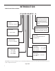
TROUBLESHOOTING Electrical Troubleshooting Chart - Cooling 9K Btu, 12K Btu, & 18K Btu
TROUBLESHOOTING Electrical Troubleshooting Chart - Cooling 24K Btu
TROUBLESHOOTING Electrical Troubleshooting Chart - Heat Pump HEAT PUMP MODE System cools when heating is desired Is line voltage present at solenoid valve? NO YES Replace Solenoid Coil NO Is the solenoid coil good? Is selector switch set for heat? YES YES Is room TSTAT configured for B signal? YES NO Is the reversing valve stuck? YES Replace Solenoid Coil FIGURE 718 (TROUBLESHOOTING) 61 Configure TSTAT for B signal
TROUBLESHOOTING Troubleshooting Chart - Cooling
L1 * * * Figure 801 (80062106) * COMP RELAY RED R BLUE L2 or ACN HEAT RELAY * 1 02 FAN 3 RELAY * FAN 4 RELAY * OUTDOOR COIL SENSOR RV RELAY BLACK INDOOR COIL SENSOR FAN 2 RELAY * QUICK DISCONNECT BRKR WHITE HARNESS COMPRESSOR SWITCH CIRCUIT FAN 1 RELAY * * (TO L1) BLACK ELECTRONIC CONTROL HEAT RELAY * BLACK S 2 VOLTAGE SELECTION SWITCH SET VOLTAGE TO 230V "F" WHITE 526 C HERM C CAPACITOR BLACK 63 COIL SOLENOID WHITE JUMPER WIRE RED 535 BLUE ORANGE 530 BLAC
TO DISPLAY Figure 802 (80062107) VOLTAGE SELECTION SWITCH SET VOLTAGE TO 220V / 230V FUSE GROUND TO CHASIS BUILDING GROUND FUSE BLOCK TRANSFORMER IN 265VAC OUT 230VAC BLACK FUSE BLACK BLACK BROWN RED WHITE WHITE QUICK DISCONNECT S WHITE * RED BLACK RED BLUE CIRCUIT BREAKER SEQ 499 INSTALL MALE/FEMALE/MALE ADAPTER ( ) "F" HARNESS COMPRESSOR C AMBIENT AIR SENSOR POU 4770B SEQ 122 SERVICE DISPLAY 2 01 (FRIEDRICH-AVH MODELS) 2 2 WIRES FLA MCA MOP R BLAC K 265V 60Hz L1 * *
VOLTAGE SELECTION SWITCH SET VOLTAGE TO 230V C M CAPACITOR L1 COMPRESSOR CONTACTOR WHITE HE R * * * RED * COMP RELAY BLACK * RED BLACK 540 BLUE CIRCUIT BREAKER (TO L1) WHITE L2) (TO Figure 803 (80126039) W HITE * HEAT RELAY * "F" FAN 3 RELAY FAN 4 RELAY ** OUTDOOR COIL SENSOR 4770D SEQ 105 INDOOR COIL SENSOR 4770D SEQ 104 FAN 2 RELAY ELECTRONIC CONTROL FAN 1 RELAY * GREEN TO MOTOR MOUNT HARNESS COMPRESSOR L2 or ACN HEAT RELAY * BLACK WHITE * R C S BLAC K 65
BLAC K BLAC K TRANSFORMER IN= 265V OUT= 230V FUSE FUSE W HITE WHITE BLACK C WHITE * COMPRESSOR CONTACTOR W HITE FUSE HOLDER CAPACITOR BLAC K RED QUICK DISCONNECT W HITE W HITE * M HE R BR O W N * * COMP RELAY RED BLUE CIRCUIT BREAKER * "F" FAN 2 RELAY * OUTDOOR COIL SENSOR * FAN 1 RELAY * BLACK HE ATE R R E LAY 4770 TO MOTOR MOUNT GREEN INDOOR COIL SENSOR HEAT RELAY * * WHITE COMPRESSOR ELECTRONIC CONTROL HEAT RELAY RED BLACK BLACK * RED R C HARNESS CO
GASKET L1 TERMINAL DETAIL NUT BLACK VOLTAGE SWITCH COMP RELAY "F" HEAT RELAY L2 or ACN L2 FAN 1 RELAY FAN 2 RELAY OUTDOOR FAN MOTOR BLACK GREEN CIRCUIT BREAKER ELECTRONIC CONTROL RED HEAT RELAY WHITE L1 TO MOTOR MOUNT BLUE RED FAN 3 RELAY COIL SOLENOID WHITE WHITE WHITE FAN 4 RELAY WHITE RV RELAY BLUE RED C CAPACITOR WIRING DIAGRAM COOL, ELECTRIC HEAT, HEAT PUMP LARGE CHASSIS, 230/208V HEATERS: 7.
AMBIENT AIR SENSOR TRANSFORMER FUSE BLOCK ELECTRONIC CONTROL (REAR VIEW) SERVICE DISPLAY 230V VOLTAGE SELECTION SWITCH SET VOLTAGE TO 230V A RED A BLACK FUSE FUSE FUSE BLACK WHITE A BUILDING GROUND BLACK BLACK WHITE WHITE QUICK DISCONNECT BROWN WHITE BLACK WHITE S L1 HARNESS COMP RED CIRCUIT BREAKER WHITE HEAT RELAY ELECTRONIC CONTROL (FRONT PANEL) VOLTAGE SWITCH COMP RELAY RED COMPRESSOR CONTACTOR COMPRESSOR R 68 C BLACK RM HE BLUE 265V 60Hz 2Ø 2 WIRES FLA MCA MOP
Figure 805 (80126405) BLACK C COMPRESSOR CONTACTOR W HITE WHITE WHITE CAPACITOR 5 * BLAC K QUICK DISCONNECT W HITE M * * COMP RELAY RED BLUE CIRCUIT BREAKER C * FAN 1 RELAY * FAN 2 RELAY * OUTDOOR COIL SENSOR * GREEN TO MOTOR MOUNT IND OOR COIL SENSOR HEAT RELAY WHITE COMPRESSOR ELECTRONIC CONTROL HEAT RELAY * BLACK BLACK * RED "F" HARNESS COMPRESSOR R 69 S HE R WIRING DIAGRAM COOL, HEAT PUMP, EH, 230V 2.5, 3.4, 5.
QUICK DISCONNECT W HITE WHITE BLACK WHITE COMPRESSOR CONTACTOR C CAPACITOR W HITE BLAC K WHITE BLAC K M HE R Figure 806 (80126403) * * * COMP RELAY RED BLUE CIRCUIT BREAKER C * * FAN 2 RELAY * OUTDOOR COIL SENSOR * * FAN 1 RELAY RED WHITE BLACK IND OOR COIL SENSOR HEAT RELAY * GREEN FAN 3 RELAY FAN 4 RELAY * RED RED RV RELAY BLACK RED BLUE ORANGE ORANGE * * Lorem ipsum TO MOTOR MOUNT HE ATE R R E LAY WHITE COMPRESSOR ELECTRONIC CONTROL HEAT RELAY * BLACK *
BLAC K 5 BLAC K TRANSFORMER IN= 265V OUT= 230V (RE OP 40 183) FUSE FUSE RED Figure 807 (80126406) WHITE BLACK C WHITE * COMPRESSOR CONTACTOR W HITE FUSE HOLDER BR O W N CAPACITOR BLAC K QUICK DISCONNECT W HITE W HITE M BLAC K WHITE * * COMP RELAY RED BLUE CIRCUIT BREAKER C * FAN 2 RELAY * OUTDOOR COIL SENSOR * * FAN 1 RELAY RED GREEN TO MOTOR MOUNT IND OOR COIL SENSOR HEAT RELAY * WHITE COMPRESSOR ELECTRONIC CONTROL HEAT RELAY * BLACK * BLACK BLACK * RED "F"
BLAC K BLAC K TRANSFORMER IN= 265V OUT= 230V FUSE FUSE BLAC K WHITE BLAC K Figure 808 (80126404) WHITE BLACK C WHITE * COMPRESSOR CONTACTOR W HITE FUSE HOLDER WHITE BR O W N RED CAPACITOR BLAC K QUICK DISCONNECT W HITE W HITE M * * COMP RELAY RED BLUE CIRCUIT BREAKER C * * FAN 1 RELAY RED WHITE BLACK FAN 2 RELAY * OUTDOOR COIL SENSOR IND*OOR COIL SENSOR HEAT RELAY * * GREEN TO MOTOR MOUNT HE ATE R R E LAY WHITE COMPRESSOR ELECTRONIC CONTROL HEAT RELAY * BLAC
PARTS CATALOG 9K, 12K Unit Assembly Figure 901 17 18 11 16 19 20 15 21 21A 8 7 10 25 14 13 12 26 1 2 23 3 5 27 6 73 22 24 9
PARTS CATALOG 9K, 12K Unit Assembly ITEM PART NUMBER PART DESCRIPTION USED ON MODEL 1 80050636 BRACKET ELECT CNTRL VPAK SMALL CIRC-BREAKER ALL 1 2 62600601 DISPLAY SERVICE VPAK GE ALL 1 3 62601009 KIT E-CNTL SERV COOL HP VHA ALL 1 -4 62600118 ASSY E-CNTRL COOL/EH AMP JMPR ALL 1 5 80015705 PANEL CONTROL BOX PREPNTD VHA09K25RTP, VHA09K34RTP, VHA09K50RTP, VHA12K25RTP, VHA12K34RTP, VHA12K50RTP 1 5 80015706 PANEL CONTROL BOX PREPAINTED 18K265 VHA09R25RTP, VHA09R34RTP, VHA09R5
PARTS CATALOG 9K, 12K Unit Assembly ITEM PART NUMBER PART DESCRIPTION USED ON MODEL 27 61773324 SWITCH CIRCUIT BRKR 20A 230V CITR220Q2NS ALL -ITEMS ARE NON- ILLUSTRATED *ITEMS ARE NON-STOCKED, WILL NORMALLY REQUIRE 2-3 WEEKS LEAD TIME 75 Figure 901 QTY 1
PARTS CATALOG 9K, 12K Refrigeration Assy Figure 902 9 10 7 8 11 6 12 13 5 14 4 3 1 2 76
PARTS CATALOG 9K, 12K Refrigeration Assy ITEM PART NUMBER PART DESCRIPTION USED ON MODEL 1 80048057 CONDENSER COIL COIL VCS.375X3X18RC2V45B19X17H3 VHA12K25RTP, VHA12K34RTP, VHA12K50RTP, VHA12R25RTP, VHA12R34RTP, VHA12R50RTP, 1 1 80101265 CONDENSER COIL VCS .
PARTS CATALOG Figure 903 9K, 12K 208/230V 9 11 10 4 3 2 8 7 5 1 6 78
PARTS CATALOG 9K, 12K 208/230V ITEM PART NUMBER PART DESCRIPTION USED ON MODEL 1 60610616 WHEEL BLOWER TA0755 ALL 1 2 80010302 WRAPPER ASSY, INSULATED ALL 1 3 80018403 PLATE SCROLL ALL 1 4 80019002 ASSY INSUL INNERWALL BLOWER 144mm ALL 1 5 80002100 BRACKET DISCONNECT ALL 1 6 80007600 NONFUSED DISCONNECT ALL 1 7 20709185 CLAMP, CAPACITOR ALL 1 8 61080702 CAPCTR 25 MF 450V 2.0 ALL 1 9 61613600 SPRING .
PARTS CATALOG 9K, 12K 265V Figure 904 8 9 10 12 4 11 3 7 19 13 14 15 16 17 2 1 18 6 80
PARTS CATALOG VHA9K, 12K 265V Figure 904 ITEM PART NUMBER PART DESCRIPTION USED ON MODEL 1 60610616 WHEEL BLOWER TA0755 ALL 1 2 80010302 WRAPPER ASSY, INSULATED ALL 1 3 80018403 PLATE SCROLL ALL 1 4 80019002 ASSY INSUL INNERWALL BLOWER 144mm ALL 1 6 20709185 CLAMP, CAPACITOR ALL 1 7 61080702 CAPCTR 25 MF 450V 2.0 ALL 1 8 61613600 SPRING .
PARTS CATALOG 18K Unit Assembly Figure 905 7 9 8 6 5 3 10 1 82 4 2
PARTS CATALOG 18K Unit Assembly ITEM PART NUMBER PART DESCRIPTION USED ON MODEL QTY 1 80106501 ASSY LEFT PANEL INSUL PREPNTD ALL 1 2 80106401 ALL 1 3 60542007 FAN PLASTIC 16” LRG; VPAC ALL 1 4 80101011 ALL 1 5 61776905 MTR MOUNT LARGE (144mm) ALL 1 6 80102172 MTR 1/4 10P CCW FAN BLCD NAN-FENG ALL 1 7 80106601 ALL 1 8 80114102 SHROUD, VPAK LARGE FOR RING ALL 1 9 80106702 ASY TOP PANEL INSUL PREPNTD ALL 1 10 80113900 SUPPORT VPAK 24 ALL 1 -11 61814801 CONNECTOR F
Non-Illustrated Parts 13 Connector - Fresh Air 14 Exhaust Door Channel 15 Exhaust Door Slide PARTS CATALOG 24K Unit Assembly Figure 906 11 12 7 9 8 1 3 6 5 10 4 2 84 Figure 910 (24k Unit Assembly)
PARTS CATALOG 24K Unit Assembly ITEM PART NUMBER PART DESCRIPTION USED ON MODEL 1 80102010 ASSY PANEL SIDE BL-24 LF VHA24K25RTP, VHA24K34RTP, VHA24K50RTP, VHA24K75RTP, VHA24K10RTP, VHA24R25RTP, VHA24R34RTP, VHA24R50RTP, VHA24R75RTP, VHA24R10RTP 1 2 80103010 ASSY PANEL SIDE BL-24 RT VHA24K25RTP, VHA24K34RTP, VHA24K50RTP, VHA24K75RTP, VHA24K10RTP, VHA24R25RTP, VHA24R34RTP, VHA24R50RTP, VHA24R75RTP, VHA24R10RTP 1 3 60542007 FAN PLASTIC 16” LRG; VPAC ALL 1 4 80101011 SHROUD RING WATER TRAP
PARTS CATALOG 18K, 24K Refrigeration Assembly Figure 907 13 14 12 16 15 11 10 9 17 20 18 18 19 8 7 6 3 4 5 1 2 86
PARTS CATALOG 18K, 24K Refigeration Assembly 87 Figure 907 ITEM PART NUMBER PART DESCRIPTION USED ON MODEL QTY 1 80101600 UPPER RIGHT POST VHA18K25RTP, VHA18K34RTP, VHA18K50RTP, VHA18R25RTP, VHA18R34RTP, VHA18R50RTP, VHA18K75RTP, VHA18R75RTP 1 1 80101601 UPPER RIGHT POST VHA24RK25RTP, VHA24K34RTP, VHA24K50RTP, VHA24K75RTP, VHA24K10RTP, VHA24K25RTP, VHA24K34RTP, VHA24K50RTP, VHA24K75RTP, VHA24K10RTP 1 2 80101500 UPPER LEFT POST VHA18K25RTP, VHA18K34RTP, VHA18K50RTP, VHA18R25RTP, VHA18R34
PARTS CATALOG 18K, 24K Refrigeration Assembly ITEM PART NUMBER 12 PART DESCRIPTION USED ON MODEL 80106202 ASSY INNERWALL INSULATION BL-24 VHA24K25RTP, VHA24K34RTP, VHA24K50RTP, VHA24K75RTP, VHA24K10RTP, VHA24R25RTP, VHA24R34RTP, VHA24R50RTP, VHA24R75RTP, VHA24R10RTP 1 13 62050004 COIL, EVAPORATOR LES.375X4X14RC2V45A20X14H6 VHA18K25RTP, VHA18K34RTP, VHA18K50RTP, VHA18R25RTP, VHA18R34RTP, VHA18R50RTP 1 13 62050008 COIL LES.
18K Blower Assembly PARTS CATALOG Figure 908 8 10 7 6 9 5 1 4 3 2 89
PARTS CATALOG 18K Blower Assembly ITEM PART NUMBER PART DESCRIPTION USED ON MODEL 1 80113300 HEATER HOLDING BRACKET VPAK 24 VHA18K25RTP-A, VHA18K34RTP-A, VHA18K50RTP-A, VHA18R25RTP-A, VHA18R34RTP-A, VHA18R50RTP-A, VHA18K25RTP-B, VHA18K34RTP-B, VHA18K50RTP-B, VHA18R25RTP-B, VHA18R34RTP-B, VHA18R50RTP-B 1 1 80102606 HEATER HOLDING BRACKET AIRFLOW INSCREASE VHA18K25RTP-C, VHA18K34RTP-C, VHA18K50RTP-C, VHA18K75RTP-C, VHA18R25RTP-C, VHA18R34RTP-C, VHA18R50RTP-C, VHA18R75RTP-C 1 2 80102290 HEATER VP
24K Blower Assembly PARTS CATALOG Figure 909 4 3 7 8 2 1 9 91
PARTS CATALOG 24K Blower Assembly ITEM PART NUMBER PART DESCRIPTION USED ON MODEL 1 80080171 IR-310 INLET RING EVAP BLOWER PSC DIA 12" ALL 1 2 80102601 BRACKET HEATER HOLDER ALL 1 3 80102290 HEATER VPAK-A24 NXT 2.5KW 230V VHA24K25RTP 1 3 80102291 HEATER VPAK-A24 NXT 3.4KW 230V VHA24K34RTP 1 3 80102292 HEATER VPAK-A24 NXT 5.0KW 230V VHA24K50RTP 1 3 80102305 HEATER VPAK-A24 NXT 7.5KW 230V VHA24K75RTP 1 3 80102294 VHA24K10RTP 1 3 80102295 HEATER VPAK-A NXT 2.
18K 230V Control Box PARTS CATALOG Figure 910 4 5 9 3 6 7 2 8 1 93
PARTS CATALOG 18K 230V Control Box ITEM PART NUMBER PART DESCRIPTION USED ON MODEL 1 80118402 ASSY C-BOX LARGE 230-265V ALL 1 2 80118601 CONTACTOR 240VAC HCL1NU01AAC VHA18K25RTP, VHA18K34RTP, VHA18K50RTP 1 2 80118602 CONTACTOR 240/277 2 POLES HCC-2XU04GG VHA18K75RTP 3 80116907 BRACKET ELECT CNTRL VPAK LARGE CIRC-BREAKER ALL 1 4 62601009 KIT E-CNTL SERV COOL HP VHA ALL 1 5 62600118 ASSY E-CNTRL COOL/EH AMP JMPR ALL 1 6 61773324 SWITCH CIRCUIT BRKR 20A 230V CITR220Q2NS ALL
24K 230V Control Box PARTS CATALOG Figure 911 12 7 8 6 9 10 5 4 3 11 2 1 13 95
PARTS CATALOG 24K 230V Control Box ITEM PART NUMBER PART DESCRIPTION USED ON MODEL 1 80032809 ASSY CONTROL BOX VPAK 24 XL 230V ALL 1 2 61600532 STAND OFF - PCB DIA .125 ALL 4 3 80118601 CONTACTOR 240VAC HCL1NU01AAC ALL 1 4 61080703 CAPCTR 40 MF 450V 2.0” X 3.
PARTS CATALOG 18K 265V Control Box Figure 912 5 6 7 4 3 8 2 9 1 10 11 12 13 14 15 16 17 18 19 20 21 97 22
PARTS CATALOG 18K 265V Control Box 98 Figure 912 ITEM PART NUMBER PART DESCRIPTION USED ON MODEL QTY 1 80118402 ASSY C-BOX LARGE 230-265V ALL 1 2 80118601 CONTACTOR 240VAC HCL1NU01AAC VHA18R35RTP, VHA18R34RTP, VHA18R50RTP 1 2 80118602 CONTACTOR 240/277 2 POLES HCC-2XU04GG VHA18R75RTP 1 3 61643311 RELAY 230V COIL DPDT 30A 208/240VAC ALL 1 4 80116907 BRACKET ELECT CNTRL VPAK LARGE CIRC-BREAKER ALL 1 5 62601009 KIT E-CNTL SERV COOL HP VHA ALL 1 6 62600118 ASSY E-CNTRL C
24K 265V Control Box PARTS CATALOG Figure 913 9 10 8 7 6 11 5 4 3 12 2 13 14 15 1 16 25 17 18 19 20 21 22 23 99
PARTS CATALOG 24K 265V Control Box ITEM PART NUMBER PART DESCRIPTION USED ON MODEL 1 80032802 ASSY CONTROL BOX VPAK 24 XL 265V ALL 1 2 61600532 STAND OFF - PCB DIA .125 ALL 4 3 61080703 CAPCTR 40 MF 450V 2.0" X 3.
AVAILABLE ACCESSORIES ACCESSORIES ARCHITECTURAL LOUVER VPAL2 and VPSC2 Extruded aluminum grille that attaches to the outdoor section of the wall plenum. VPSC2 can be ordered in custom colors. DIMENSIONS: 25 9/16" W x 31 1/16" H WALL PLENUM (Required) VPAWP1-8, VPAWP1-14 Two-part sleeve that telescopes in and out; sits inside the exterior wall penetration.
WARRANTY Friedrich Air Conditioning Co. 10001 Reunion Place, San Antonio, TX 78216 800.541.6645 www.friedrich.com VERT-I-PAK® A SERIES SINGLE PACKAGED VERTICAL AIR CONDITIONERS LIMITED WARRANTY SAVE THIS CERTIFICATE. It gives you specific rights. You may also have other rights which may vary from state to state and province to province In the event that your unit needs servicing, contact your nearest authorized service center.
CUSTOMER SATISFACTION and QUALITY ASSURANCE Friedrich is a conscientious manufacturer, concerned about customer satisfaction, product quality, and controlling warranty costs. As an Authorized Service Provider you play a vital role in these areas. By adhering to the policies and procedures you provide us with vital information on each warranty repair you complete.