
Service and Parts Manual (2019, 2020, 2021, 2022)
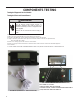

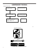
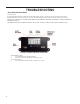
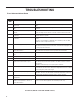
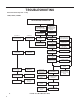
Table Of Contents
- INTRODUCTION
- Important Safety Information
- Personal Injury Or Death Hazards
- Operation of Equipment in During Construction
- Equipment Identification
- Model and Serial Number Location
- Model and Serial Number information is found on the Manufacturer’s DATA TAG, located on the front or top.
- Model Number Reference Guide
- Serial Number Reference Guide
- General Specifications
- Chassis Specifications 9K, 12K
- 18K Dimensions
- 24K Dimensions
- Electrical Data
- Electrical Requirements
- Electrical Ratings Table
- Supply Air Flow and Data
- Electronic Control Board Features
- Electronic Sequence of Operation
- Compressor Lock Out Time
- Cooling Fan Delay
- Heating Fan Delay
- Fan Speed Change Delay
- Room Air Sampling Feature
- Low Voltage Interface Connections
- Interface Connector Definitions
- Remote Wall Thermostat
- Remote Wall Thermostat Location
- Desk Control
- Auxiliary Fan Control
- Unit Heat Control Operation - Heat Pump With Electric Heat
- Refrigeration Sequence Of Operation
- Remove The Chassis
- Servicing / Chassis Quick Changeouts
- To Remove the Chassis from the Closet:
- Refrigerant Charging
- Undercharged Refrigerant Systems
- Overcharged Refrigerant Systems
- Restricted Refrigerant System
- Sealed System Method of Charging/ Repairs
- Checking External Static Pressure
- Explanation of charts
- Indoor Airflow Data
- Ductwork Preparation
- Fresh Air Door
- Checking Approximate Airflow
- Electric Heat Strips
- COMPONENT TESTING
- Hermetic Components Check
- Reversing Valve Description And Operation
- Testing The Reversing Valve Solenoid Coil
- Checking The Reversing Valve
- Touch Test Chart : To Service Reversing Valves
- Compressor Checks
- Compressor Replacement -Special Procedure in Case of Compressor Burnout
- Fan Motor
- Capacitors
- Heating Element and Limit Switch
- Heater Elements And Limit Switches’ Specifications
- Drain Pan Valve
- Thermistor Resistence Values (This Table Applies to All Thermistors)
- Testing the Diagnostic Service Module
- Testing the Electronic Control Board
- Electronic Control Board Components Identification And Testing
- 24k Indoor Blower Motor
- Error Codes and Alarm Status
- Electrical Troubleshooting Chart - Cooling
- 9K Btu, 12K Btu, & 18K Btu
- 24K Btu
- Electrical Troubleshooting Chart - Heat Pump
- Troubleshooting Chart - Cooling
- 9-12K 208/230V
- 9-12K 265V
- 18K 208/230V (2.5KW, 3.5KW, 5KW)
- 18K 265V (2.5KW, 3.5KW, 5.0KW)
- 18K 208/230V (7.5KW)
- 18K 265V (7.5KW)
- 24K 208/230V (2.5KW, 3.5KW, 5KW)
- 24K 208/230V (7.5KW AND 10KW)
- 24K 265V (2.5KW, 3.5KW, 5KW)
- 24K 265V (7.5KW and 10KW)
- 9K, 12K Unit Assembly
- 9K, 12K Refrigeration Assy
- 9K, 12K 208/230V
- 9K, 12K 265V
- 18K Unit Assembly
- 24K Unit Assembly
- 18K, 24K Refrigeration Assembly
- 18K Blower Assembly
- 24K Blower Assembly
- 18K 230V Control Box
- 24K 230V Control Box
- 18K 265V Control Box
- 24K 265V Control Box

54 PB
COMPONENTS TESTING
Testing the Diagnostic Service Module
Testing the Electronic Control Board
WARNING
ELECTRIC SHOCK HAZARD
Turn off electric power before service or
installation. Extreme care must be used, if it
becomes necessary to work on equipment with
power applied.
Failure to do so could result in serious injury or
death.
If the Diagnostic Service Module does not turn on:
1. Make sure there is 208/230 VAC to the unit and that it is turned on.
2. Disconnect the diagnostic service module’s wire harness on the control board.
3. Using a voltmeter, check the fi rst two pins to the left of the female connector (see picture below).
There should be up to 5VDC.
4. If there is no voltage, replace the electronic control board.
5. If there is voltage, check the wire harness and connections at the electronic control board and the diagnostic
service module.
6. IF THE CONNECTIONS AND THE WIRE HARNESS ARE GOOD, REPLACE THE DIAGNOSTIC SERVICE MODULE.
FIGURE 711 (DIAGNOSTIC SERVICE MODULE)
FIGURE 712 (SERVICE MODULE CONNECTOR)
TEST HERE UP TO 5VDC.
IF NO VOLTAGE, REPLACE BOARD.
IF THERE IS 5VDC, CHECK CONNECTIONS AND CABLE.
IF OK, REPLACE SERVICE MODULE.