
Service and Parts Manual (2019, 2020, 2021, 2022)
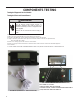

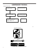
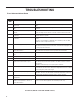
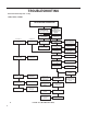
Table Of Contents
- INTRODUCTION
- Important Safety Information
- Personal Injury Or Death Hazards
- Operation of Equipment in During Construction
- Equipment Identification
- Model and Serial Number Location
- Model and Serial Number information is found on the Manufacturer’s DATA TAG, located on the front or top.
- Model Number Reference Guide
- Serial Number Reference Guide
- General Specifications
- Chassis Specifications 9K, 12K
- 18K Dimensions
- 24K Dimensions
- Electrical Data
- Electrical Requirements
- Electrical Ratings Table
- Supply Air Flow and Data
- Electronic Control Board Features
- Electronic Sequence of Operation
- Compressor Lock Out Time
- Cooling Fan Delay
- Heating Fan Delay
- Fan Speed Change Delay
- Room Air Sampling Feature
- Low Voltage Interface Connections
- Interface Connector Definitions
- Remote Wall Thermostat
- Remote Wall Thermostat Location
- Desk Control
- Auxiliary Fan Control
- Unit Heat Control Operation - Heat Pump With Electric Heat
- Refrigeration Sequence Of Operation
- Remove The Chassis
- Servicing / Chassis Quick Changeouts
- To Remove the Chassis from the Closet:
- Refrigerant Charging
- Undercharged Refrigerant Systems
- Overcharged Refrigerant Systems
- Restricted Refrigerant System
- Sealed System Method of Charging/ Repairs
- Checking External Static Pressure
- Explanation of charts
- Indoor Airflow Data
- Ductwork Preparation
- Fresh Air Door
- Checking Approximate Airflow
- Electric Heat Strips
- COMPONENT TESTING
- Hermetic Components Check
- Reversing Valve Description And Operation
- Testing The Reversing Valve Solenoid Coil
- Checking The Reversing Valve
- Touch Test Chart : To Service Reversing Valves
- Compressor Checks
- Compressor Replacement -Special Procedure in Case of Compressor Burnout
- Fan Motor
- Capacitors
- Heating Element and Limit Switch
- Heater Elements And Limit Switches’ Specifications
- Drain Pan Valve
- Thermistor Resistence Values (This Table Applies to All Thermistors)
- Testing the Diagnostic Service Module
- Testing the Electronic Control Board
- Electronic Control Board Components Identification And Testing
- 24k Indoor Blower Motor
- Error Codes and Alarm Status
- Electrical Troubleshooting Chart - Cooling
- 9K Btu, 12K Btu, & 18K Btu
- 24K Btu
- Electrical Troubleshooting Chart - Heat Pump
- Troubleshooting Chart - Cooling
- 9-12K 208/230V
- 9-12K 265V
- 18K 208/230V (2.5KW, 3.5KW, 5KW)
- 18K 265V (2.5KW, 3.5KW, 5.0KW)
- 18K 208/230V (7.5KW)
- 18K 265V (7.5KW)
- 24K 208/230V (2.5KW, 3.5KW, 5KW)
- 24K 208/230V (7.5KW AND 10KW)
- 24K 265V (2.5KW, 3.5KW, 5KW)
- 24K 265V (7.5KW and 10KW)
- 9K, 12K Unit Assembly
- 9K, 12K Refrigeration Assy
- 9K, 12K 208/230V
- 9K, 12K 265V
- 18K Unit Assembly
- 24K Unit Assembly
- 18K, 24K Refrigeration Assembly
- 18K Blower Assembly
- 24K Blower Assembly
- 18K 230V Control Box
- 24K 230V Control Box
- 18K 265V Control Box
- 24K 265V Control Box

59 PB
TROUBLESHOOTING
Electrical Troubleshooting Chart - Cooling
9K Btu, 12K Btu, & 18K Btu
FIGURE 716 (TROUBLESHOOTING)