
Installation & Operation Manual (2019)


8
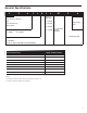
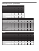
Supply Air Flow Data
Indoor CFM & External Static Pressure
Model
VEA24 VHA18 VHA24
Fan Speed
Low High Low High Low High
ESP (“)
CFM
.10”
610
700 420 465 610 700
.15”
585 670 390 420 585 670
.20”
560 640 345 380 560 640
.25”
535 610 300 325 535 610
.30”
510 580 255 280 510 580
Indoor air ow may be determined by measuring the external static pressure (ESP) of the duct system using an inclined
manometer or magnahelic gauge and consulting the above chart to derive actual air ow. Under no circumstances
should the large chassis Vert-I-Pak equipment be operated at an external static pressure in excess of 0.4” W.C. Op-
eration of the Vert-I-Pak under these conditions will result in inadequate air ow, leading to poor performance and/or
premature component failure.
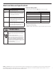
Control
For LOW speed only operation, connect the fan output terminal from the thermostat to the GL terminal of the electronic
control.
For HIGH speed only operation, connect the fan output terminal from the thermostat to the GH terminal of the electronic
control.
For thermostats with two-speed capability, connect the LOW speed output to the GL terminal and the HIGH speed output
to the GH terminal.