Installation & Operation Manual VERT-I-PAK® A-Series Single Package Vertical Air Conditioning System Large Chassis NOTE: This manual only applies to VEA 24000 and VHA 18000-24000 BTU/hr models.
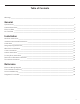
Table of Contents Warnings___________________________________________________________________________________ 3 General Specifications_______________________________________________________________________________ 4 Chassis Dimensions__________________________________________________________________________5 Electrical Data______________________________________________________________________________ 6 Air Flow Data_______________________________________________________________________________ 8 Installa
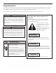
Congratulations! The Friedrich VPAK has been carefully engineered and manufactured to provide many years of dependable, efficient operation while maintaining a comfortable temperature and humidity level. Many extra features have been built into the unit to ensure quiet operation, optimal circulation of cool, dry air, and the most economic operation. Please carefully read and follow the installation instructions and safety warnings detailed in this manual.
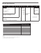
General Specifications V E A 2 4 Series K 3 4 RT -A Electric Heat Size VEA = Cooling + Electric Heat 25 = 2.5 kW VHA = Heat Pump + Electric Heat 34 = 3.4 kW Nominal Capacity (Btu /Hr.) RT = Standard 75 = 7.5 kW Remote Operation 18 = 18000 P Engineering Code 50 = 5.
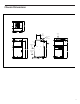
Chassis Dimensions 24 3/8 22 15/16 TOP SUPPLY AIR 10 DUCT DIAMETER ELECTRICAL ENTRY BOTH SIDES 5 1/16 2 3/16 2 1/2 RETURN AIR CONDENSER INLET AIR 39 3/4 42 5/8 47 15/16 31 CONDENSER EXHAUST AIR FRONT 11 11/16 1 1/2 SIDE REAR 5
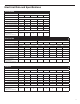
Electrical Data and Specifications VEA 230/208 MODEL VEA24K 2500/2050 3400/2780 5000/4090 10.9/9.9 14.8/13.4 Minimum Circuit Ampacity 17.2 Branch Circuit Fuse (Amps) 20 Heater Watts 7500/6135 10000/8180 21.7/19.7 32.6/29.5 43.5/39.3 22.1 30.7 44.3 57.9 25 35 45 60 230/208 Voltage Elec. Heating Current (Amps) LRA - Compressor (Amps) Cooling Current (Amps) Basic Heater Size 46.0 46.0 46.0 46.0 46.0 10.0/10.4 10.0/10.4 10.0/10.4 10.0/10.4 10.0/10.4 2.5 kW 3.4 kW 5.
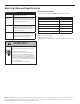
Electrical Data and Specifications Electrical Requirements Wire Size Use ONLY wire size recommended for single outlet branch circuit. Fuse/Circuit Breaker Use ONLY type and size fuse or HACR circuit breaker indicated on unit’s rating guide. Proper over current protection to the units is the responsibility of the owner. Grounding Wire Sizing Unit MUST be grounded from branch circuit to unit, or through separate ground wire provided on permanently connected units.
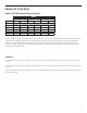
Supply Air Flow Data Indoor CFM & External Static Pressure Model VEA24 Fan Speed Low VHA18 High Low VHA24 High Low High CFM ESP (“) .10” 610 700 420 465 610 700 .15” 585 670 390 420 585 670 .20” 560 640 345 380 560 640 .25” 535 610 300 325 535 610 .
Vert-I-Pak Required Minimum Clearances Building Exterior Unit Opening Requirements VPAK units must be installed on an outside wall. Confined spaces and/or covered areas should be avoided. Units must be installed no closer than 12” apart when two units are side by side. If three or more units are to operate next to one another, maintain a minimum of 60” between units or pairs of units (Figure B).
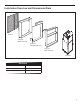
Installation Overview and Dimensional Data VPAL2 Exterior Wall Plenum Exterior Rough Opening Interior Wall Plenum Chassis Dimensions Chassis (W x D x H) 23 1/8” x 23 1/8” x 47 1/4” Exterior Rough Opening (W x H) Closet Rough Opening (W x H) 24 5/8” x 30 7/8” 27” x 55 3/4” 10
Closet View Example Closet Optional 25” x 20” access panel filter (field supplied) Rigid Ductwork Exterior Wall Electrical Connection Flexible Ductwork VPRG4/R Access Panel and Return Air Grille VPAWPX-XX Wall Plenum Optional Platform Minimum 3” clearance on all three sides required for air flow, service, and installation NOTE: It is recommended that 6” of clearance is provided on the side where the primary condensate is plumbed.
Wall Opening Dimensions Exterior Wall Plenum Cut-Out Dimensions (W x H): 24 5/8” x 30 7/8” 1 1/2” NOTE: The distance between the rough opening and the finished floor/platform must be 1 1/2”. If the installation will utilize an auxiliary drain pan it may not exceed 1 1/2” in height.
Wall Plenum Installation Parts included in Plenum kit: B Outside Plenum Half (Part A) Inside Plenum Half (Part B) A Field Supplied Parts: Sealant, attachment screws, and flashing are field supplied. Silicone sealant is recommended. Flashing Sealant VPAWP-8 adjust for walls up to 4”- 8” thick. VPAWP-14 adjust for walls up to 8” - 14” thick Shim All installations are similar.
Wall Plenum Installation Step 1 - Outside Wall Plenum Half Note: The wall plenum is not designed to carry any structural load. A load bearing header must be built above the rough opening. 1. Prepare the rough opening. The rough opening should be lined with metal or wood. The plenum will warp if sealed against concrete or brick. 2. Dry fit the outside plenum half into the rough opening and check the fit and level. 3.
Wall Plenum Installation Step 2 - Inside Wall Plenum Half Caulk all 8 Flange Corners and Unused Holes Detail A 1. Apply sealant to all 4 flange corners and unused holes. See Detail A. 2. Flash the inside of the rough opening to ensure the proper fit and level. 3. Insert inside plenum half (Part B) into outside plenum half (Part A). Ensure that Part A does not back out of the rough opening. 4. Remove the inside plenum half. 5.
Wall Plenum Installation Step 3 - Inside Wall Plenum (cont.) B Detail B NOTE: Do not place any screws, fasteners, or penetrating holes through the top or bottom of the plenum assembly. 1. Drill pilot holes on the interior of the inside plenum half (Part B) as show in Detail B. Pilot holes should be located approximately 4” from the top and bottom of the inside plenum half, on both the left and right sides. 2. Install fasteners through each pilot hole. Fastener must pass through both Part A and Part B.
Drain Kit Installation Step 4 - VPDP1 Installation A NOTE: VPDP1 (Drain Kit) should be installed prior to the installation of the chassis. 1. 2. 3. 4. 5. 6. Cut the weather seal gasket at the left corner of the plenum. From the initial cut, measure 8” toward the center of the plenum and make a second cut. Peel away the cut section of gasket from the plenum surface. Run a 1/4” bead of sealent the entire width of the removed gasket.
Louver Installation Installation of the louver PRIOR to wall plenum installation 1. 2. Hold the louver up to the outside plenum half (Part A) and line up the louver top with the very top edge of the ¾” flange. Line up the wall plenum holes with the threaded holes in the louver and securely tighten fasteners. Installation of the louver AFTER the installation of wall plenum on elevated floors From the interior of the utility closet: 1.
Final Wall Plenum and Architectural Louver Installation Louver NOTE: Ensure that the weather strip is undamaged and provides a continuous seal around the inner perimeter of the plenum. Apply silicone grease or other non-petroleum-based lubricants to the weather strip to enhance the sealing capability of the weather strip and ease installation of the air conditioner chassis. 1. Loosen the two set screws located on the top side of the divider. 2.
Chassis Installation A 1. Ensure that the wall plenum and louver are installed in accordance with the instructions listed on pages 13-18. 2. Place the chassis into the closet with the outdoor side facing the wall plenum opening. 3. Slide the chassis into the wall plenum until the plenum divider seal is established. NOTE: The Vert-I-Pak chassis must be inserted into the wall plenum so that the plenum divider gasket makes contact with the plastic condenser baffle on the unit.
Primary Drain Installation Nipple 3/4” PVC/NPT Union 3/4” FTP/SLIP Supplied 3/4” plugs Threaded end Example of field supplied DWV system Slip end NOTE: Failure to follow the following procedures may result in serious property damage. A field supplied secondary condensate pan or P-trap may be required. Check with local codes. In case of drainage system blockage, the unit base will allow excess water to flow out of the unit through the plenum and the architectural louver.
Indoor Return Air Grille and Ductwork Installation Option 1 Option 2 VPRG4/R Return Air Grille with Access Panel A field-supplied (25” x 20”) can be mounted inside the hinged access door. The door can be installed with the grille oriented at the top of the panel for improved sound attenuation. Field Supplied Return Air Grille A field supplied return air grille divorced from the access panel must have a minimum 250 square inches of free area.
Remote Thermostat and Low Voltage Control Connection Remote Thermostat Auxiliary Fan Control All Friedrich Vert-I-Pak units are factory configured to be controlled by using a single stage heat/cool remote wall mounted thermostat. The thermostat may be auto or manual changeover as long as the control configuration matches that of the Vert-I-Pak unit. The Friedrich Vert-I-Pak also has the ability to control a 24VAC relay to activate an auxiliary or transfer fan.
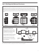
VEA 230/208 Electrical Wiring Diagram WASHER GASKET NUT TERMINAL DETAIL BLACK COMPRESSOR C " F" RED L1 WHITE FUSE FUSE HOLDER FAN 2 RELAY FAN 3 RELAY C FAN 4 RELAY RV RELAY CAPACITOR N FA WIRING DIAGRAM COOL, ELECTRIC HEAT SMALL CHASSIS, 230/208V HEATERS: 2.5KW, 3.4KW, 5.
VHA 230/208 Electrical Wiring Diagram WASHER C S HARNESS COMPRESSOR COMPRESSOR COMP RELAY " F" BLACK L1 RED QUICK DISCONNECT L2 WHITE (IF APPLICABLE) FAN 2 RELAY FAN 3 RELAY C FAN 4 RELAY RV RELAY CAPACITOR M COIL SOLENOID FUSE FUSE HOLDER RED FAN 1 RELAY N FA WIRING DIAGRAM COOL, ELECTRIC HEAT, HEAT PUMP SMALL CHASSIS, 230/208V HEATERS: 2.5KW, 3.4KW, 5.
VHA 265 Electrical Wiring Diagram WASHER GASKET A F US E NUT BLACK WHITE FUSE BLOCK COMPRESSOR C HARNESS COMPRESSOR S F US E TRANSFORMER " F" BLACK L2 RED FAN 1 RELAY WHITE FAN 2 RELAY RED C CAPACITOR COIL SOLENOID RV RELAY WHITE BROWN GREEN BLACK MOTOR BLUE OUTDOOR COIL SENSOR HEATER 2.5 KW & 3.4 KW 5.0 KW FAN 4 RELAY ORANGE RELAY FAN 3 RELAY N FA WIRING DIAGRAM COOL, ELECTRIC HEAT, HEAT PUMP SMALL CHASSIS, 265V HEATERS: 2.5KW, 3.4KW, 5.
Final Checklist FinalInstallation Installation Checklist Chassis Operation Chassis Operation Fresh Air Door Cooling Operation The fresh air door is an “intake” system. It is opened via a slide mechanism on the front of the The chassis set point must be at least 3°F below room located just above the indoor coil. Move temperature to ensure compressor operation. the slide left to open and right to close the door.
Service & Warranty Servicing / Chassis Quick Change Outs The chassis is designed for quick disconnect and change out. For minor electrical service, the control box cover lifts straight up after the screws and disconnect pull-out are removed. For major electrical,refrigeration, and fan service the chassis should be removed from the utility closet. Electrical Shock Hazard Pull out electrical disconnect on front of the chassis and turn off all power to unit before servicing.
Diagnostic Error Codes Unit Control Panel The display has four (4) digits. The left two digits indicate the error code (1-24) and the “On/Off” icons above these digits indicate the current state of the error code. The right two digits show the history count (up to 99) of the associated error. The display contains a maintenance icon (wrench) that will illuminate when the unit requires maintenance.
THIS PAGE INTENTIONALLY LEFT BLANK.