
Accessory VPASA1 Manual (2020)


VPASA1 KIT
Pg 14/16
95303000_02
Friedrich Air Conditioning Co.
10001 Reunion Place Suite 500/ San Antonio, Texas 78216
(210) 546-0500 / (800) 541-6645 / www.friedrich.com
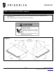
Lift and place new Vert-I-Pak unit (along with attached adapter) onto tray and push flush against
existing sleeve. When correctly installed, sleeve gasket will press against top of adapter.
The top of adapter will overlap the top of the existing sleeve. Secure with at least 2 #8 sheet metal
self-drilling screws through the pre-punched holes immediately. This will hold the unit in position.
(See Figure 11A)
Note: If using the 90° bent flange (the First Company® sleeve is flush with the inner wall), secure the flange
to the wall. (See Figure 11B)
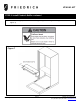
Measure the height from the bottom of the Vert-I-Pak to the floor. (See “H” in Figure 11) height
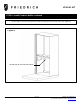
o Height (H) 12” or less: bracket + bracket stand (See Figure 12A)
Slide 2 stand bracket into front isolating foot
Place supplied cage nut at the bottom of the extension angle
Insert supplied leg bolt and turn it all the way to end of the thread
Install extension angle to approximate 1 inch above the ground
Secure with at least 2 screws
Unscrew till tight
o Height (H) more than 12”: bracket + wood stand (See Figure 12B)
Slide 2 stand bracket into front isolating foot
Premeasure and cut wood to proper length. Total 2 pieces of wood studs.
Slide wood stud into stand bracket and secure, using at least 2 field supplied #8
screws per side. (total of 2 screws per stand, 4 for both stands)
Refer to the Vert-I-Pak A-Series Installation and Operation Manual to complete the installation
(Electrical, Condensate Drain, Supply Air, etc). Do not unplug the front drain.
Step 9: Vert-I-Pak and Stand Installation
Important! Make sure you read all directions below before starting this step.