Vert-I-Pak® Single PackageVertical Air CenditieningSystem A-Series 9,000 I 12,000 I 18,000 BTU/h Installation& OperationManual 920-075-07 (10-03)
920-075-07 (10-03) Tableof Contents GeneralSpecifications IL 3 Model Number Identification Guide ................................................................................................................................... 4 VERT-I-PAKChassisSpecifications .................................................................................................................................... 4 Installation 1. 2. UtilityClosetDimensions...............................................................
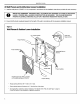
920-075-07 (10-03) Vert-I-Pak Installation Recommendations Forproperunitperformanceand maximumoperatinglife please refer to the minimuminstallationclearancesbelow. Figure I VERT-I-PAK ® units must be installed on an outside wall. Confined spaces and/or covered areas should be avoided. Units should be installed no closer than 12" apart when two units are side by side. If three of more units are to operate next to one another allow a minimum of 60" between units or pairs of units.
920-075-07 (10-03) Section I. GeneralSpecifications V MODEL NUMBER A ENGINEERING SERIES V=Vertical Series E=Cooling with or without electric heat H=Heat Pump CODE OPTIONS RT = Standard Remote Operation SP = Seacoast Protected ELECTRIC HEATER SIZE A-Series 00 = No electric heat 25 = 25 KW 34 = 3.4 KW 50 = 5.
920-075-07 (10-03) II. Installation 1) Utility ClosetDimensions Recommended utility closet dimensions and a typical indoorinstallation are illustrated in Figure 3. Three inches minimum clearance on three sides of the unit must be allowed for return airflow, installation access and service access. See Figures 3 and 4 for clearances and reference dimensions.
920-075-07 (10-03) 2) Wall PlenumandArchitectural LouverInstallation A, Install the wall plenum (VPAWP1-8/1-14) components in accordance with the installation instructions provided with each accessory, LOADS. PROPER WALL HEADER CONSTRUCTION IS REQUIRED. THE PLENUM REQUIRES IMPORTANT REMINDER: FRIEDRICH WALL PLENUM IS NOT DESIGNED TO CARRY STRUCTURAL PROPER FLASHING, SHIM AND CAULK FOR A WEATHER RESISTANT INSTALLATION.
920-075-07 (10-03) 3) Electrical Data Electrical Data Model Voltage (V) LRA - Comp. (A) Cooling Current (A) MIN. Ckt. Amps (A) 230/208 230/208 230/208 230/208 230/208 / 230/208 230/208 230/208 230/208 21 21 21 24.0 24.0 24.0 47 47 47 4.4/4.9 4.4/4.9 5.5/6.1 5.5/6.1 5.5/6.1 9.2/10.2 9.2/10.2 9.2/10.2 20 30 15 20 30 15 20 30 4.4/4.
920-075-07 (10-03) 3) ElectricalData (continued) Electrical RatingTables Figure6 Electrical Requirements NOTE: Use copper conductors NEC Note:All field wiring must comply with NEC and local codes. It is the responsibility of the installerto insurethat the electrical codes are met. Wire Size Use ONLY wiring size recommended for single outlet branch circuit.
20-075-07 (10-03) 3) ElectricalData (continued) Figure7 Electrical & Thermostat Wiring Diagrams FOR 208 VOLT MODELS ONLY: MOVE THE WHITE WIRE AS SHOWN BELOW THERMOSTAT CONNECTIONS (REAR) COM. 208V 240V TRANSFORMER RT2 THERMOSTAT (FRONT) 24V T-STAT DEFROST HEATER COOL RELAY 1 Note: the diagram above illustrates the typical thermostat wiring and 208 volt transformer wiring.
920-075-07 (10-03) 4) IndoorReturnAir Grille Installation There are three Indoor Return Air Grille options as shown in Figure 8, Choose the option that best suits your needs. Use the installation instructions provided with accessories for installation details, Figure8 ReturnAir Grille Options Option I VPRG4 Return Air Grille with Access Panel A field-supplied(25"x 20")filter is mountedinsidethe hingedaccessdoor. _ I _ ....... _ _\_ _÷ VPRG2 Return Air Grille Unitrequiresa field-supplied accessdoo
920-075-07 (10-03) 5) DuctworkPreparation 6) ChassisInstallation 1) Duct ESP: Install the following components as shown in Figure 5. To determine your system's indoor external static pressure (ESE in inches of water) use a duct calculator (as provided by your duct supplier). Include all flex duct transitions and discharge grille(s). If flex duct is used, be sure all the slack is pulled out of the flex duct. Flex duct ESP can increase considerably when not fully extended. DO NOT EXCEED a total of .
920-075-07 (10-03) 7) ChassisFinal Connections With the chassis in place, you are now ready to begin chassis connections: A. Move the thermostat switches to "OFF" and "AUTO." This will keep the thermostat from cycling the chassis until final connections are complete. B. Connecttheductworkontothel0"coilar. Plasticwireties(field supplied)are suggested to secure the ductwork inplace. Use 2 wire ties, one for each inner and outer flex duct sleeve.
920-075-07 (10-03) III. ChassisOperation IV. Service& Warranty 9) Remote Thermostat Control 14) Servicing/Chassis QuickChangeouts The chassis requiresa simple singlestage heat-cool wall thermostat. Each chassis comes with a terminal strip located in the electrical control box. All internalchassis wiring (low & high voltage) isfactory ready for 230 Volt operation. For 208 Volt operation a single wire MUST BE CHANGED ON THE TRANSFORMER. Refer to Figure 7 on page 9.
920-075-07 FRIEDRICH Post Office (10-03) AIR CONDITIONING CO. Box 1540 • San Antonio, Texas 78295-1540 (210) 357-4400. FAX (210) 357-4480 VERT- I-PAK ®A SERIES SINGLE PACKAGE VERTICAL AIR CONDITIONERS LIMITED WARRANTY SAVE THIS CERTIFICATE. to province. it gives you specific rights, you may also have other rights which may vary from state to state and province In the event that your unit needs servicing, contact your nearest authorized service center.
920-075-07 (10-03) V. Vert-I-Pak Accessories MODEL DESCRIPTION VPAWP1-8 WALL PLENUM Two-part sleeve that telescopes in and out from 5 _/2"to 8" in depth. The wall plenum sits inside the exterior wall penetration. DIMENSIONS: 303&" high x 24W' wide. CUTOUT DIMENSIONS: 30W' high x 24_&" wide. VPAWP1-14 Same as VPAWP1-8, but telescopes 8" to 14" as required. ARCHITECTURAL LOUVER Extruded aluminum louver VPAL2 that attaches to the outdoor section of the wall plenum.
Friedrich AirConditioning Co. Post Office Box15401 SanAntonio, TX78295-1540 4200N,PanAmExpressway LSanAntonio, TX78218-5212 (210) 357-4400 fax(210) 357-4480 www, friedrich.com Printed in the U.S.A.