Service/ Parts Manual VERT-I-PAK Standard Chassis Models - 09K25RTN, 09K34RTN, 09K50RTN, 09K25RTP, 09K34RTP, 09K50RTP 9K VEA VHA - 09K25RTN, 09K34RTN, 09K50RTN, 09R25RTN, 09R34RTN, 09R50RTN - 12K25RTN, 12K34RTN, 12K50RTN,12K25RTP, 12K34RTP, 12K50RTP 12K VEA VHA - 12K25RTN, 12K34RTN, 12K50RTN, 12R25RTN, 12R34RTN, 12R50RTN 18K 24K 1 95992010_01 VEA - 18K25RTP, 18K34RTP, 18K50RTP VHA - 18K25RTN, 18K34RTN, 18K50RTN, 18R25RTN, 18R34RTN, 18R50RTN VEA - 24K10RTP, 24K25RTP, 24K34RTP, 24K50RTP, 24K75RTP VHA - 24
Table of Contents INTRODUCTION 4 Important Safety Information 4 Personal Injury Or Death Hazards 5 Operation of Equipment in During Construction 7 Equipment Identification 8 Model and Serial Number Location 8 Model and Serial Number information is found on the Manufacturer’s DATA TAG, located on the front or top.
Electronic Control Board Components Identification And Testing TROUBLESHOOTING Error Codes and Alarm Status Electrical Troubleshooting Chart - Cooling 9K Btu, 12K Btu, & 18K Btu 24K Btu Electrical Troubleshooting Chart - Heat Pump Troubleshooting Chart - Cooling WIRING DIAGRAMS 9-18K VEA 208/230V 9-18K VHA 208/230V 9-18K VHA 265V 24K VEA 208/230V 2.5/3.4/5.0 24K VEA 208/230V 7.5/10.0 24K VHA 208/230V 2.5/3.4/5.0 24K VHA 208/230V 7.5/10 24K VHA 265V 2.5/3.4/5.0 24K VHA 265V 7.5/10.
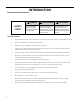
INTRODUCTION Important Safety Information The information in this manual is intended for use by a qualified technician who is familiar with the safety procedures required for installation and repair, and who is equipped with the proper tools and test instruments required to service this product.
Personal Injury Or Death Hazards INTRODUCTION WARNING SAFETY FIRST Do not remove, disable or bypass this unit’s safety devices. Doing so may cause fire, injuries, or death. AVERTISSEMENT Ne pas supprime, désactiver ou contourner cette l´unité des dispositifs de sécurité, faire vous risqueriez de provoquer le feu, les blessures ou la mort. ADVERTENCIA No eliminar, desactivar o pasar por alto los dispositivos de seguridad de la unidad. Si lo hace podría producirse fuego, lesiones o muerte.
INTRODUCTION PERSONAL INJURY OR DEATH HAZARDS 6 • REFRIGERATION SYSTEM REPAIR HAZARDS: • Use approved standard refrigerant recovering procedures and equipment to relieve high pressure before opening system for repair. • Do not allow liquid refrigerant to contact skin. Direct contact with liquid refrigerant can result in minor to moderate injury. • Be extremely careful when using an oxy-acetylene torch. Direct contact with the torch’s flame or hot surfaces can cause serious burns.
INTRODUCTION Operation of Equipment in During Construction • OPERATION OF EQUIPMENT MUST BE AVOIDED DURING CONSTRUCTION PHASES WHICH WILL PRODUCE AIRBORNE DUST OR CONTAMINTES NEAR OR AROUND AIR INTAKE OPENINGS: • Wood or metal framing; • Drywalling or sheathing, • Spackling or applying joint compound. • Sanding or grinding. • Moulding or trimwork.
INTRODUCTION This service manual is designed to be used in conjunction with the installation and operation manuals provided with each air conditioning system. This service manual was written to assist the professional service technician to quickly and accurately diagnose and repair malfunctions. Installation procedures are not given in this manual. They are given in the Installation and Operation Manual which can be aquired on the Friedrich website (www.friedrich.com).
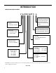
INTRODUCTION Model Number Reference Guide V E A 09 K 34 RT P - A SERIES V=VERTICAL SERIES FUNCTION E - ELECTRIC HEAT H - HEAT PUMP ENGINEERING REVSION LETTER INDICATES AN ENGINEERING MODIFICATION TO AN EXISTING MODEL MARKETING SUFFIX LETTER INDICATES MODIFICATION TO AN EXISTING MODEL SERIES OPTIONS RT = STANDARD REMOTE OPERATION DESIGN SERIES A = 32”/47” CABINET NOMINAL CAPACITY A SERIES (Btu/h) 09= 9,000 12 = 12,000 18 = 18,000 24 = 24,000 ELECTRIC HEATER SIZE A SERIES 25 = 2.5 KW 75 = 7.
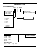
INTRODUCTION Serial Number Reference Guide 17 12 M 00001 NUMERIC SEQUENCE FIRST UNIT OF EACH MONTH = 00001 YEAR OF MANUFACTURE 17 = 2017 18 = 2018 19 = 2019 20 = 2020 21 = 2021 22 = 2022 MONTH OF MANUFACTURE 01 = JANUARY 02 = FEBRUARY 03 = MARCH 04 = APRIL 05 = MAY 06 = JUNE 07 = JULY 08 = AUGUST 09 = SEPTEMBER 10 = OCTOBER 11 = NOVEMBER 12 = DECEMBER MANUFACTURING LOCATION Refer to the Chart below for Serial Numbers beginning with an Alpha Sequence VPAK Serial Number Identification Guide SERIAL NUMBE
Chassis Specifications SPECIFICATIONS MODEL VEA09, VEA12, VEA18, VHA09, VEA 24, VHA18, VHA 24 VHA12 Voltage 230/208 or 265 230/208 or 265 Refrigerant R-410A R-410A Chassis Width 23 1/8” 23 1/8” Chassis Depth 23 1/8” 23 1/8” Chasis Height** 32 1/4” 47 1/4” Shipping W x D x H 26 x 28 1/2” x 35” 26” x 25” x 52” Supply Factory Collar *** 10” 10” Drain Connection 3/4” FPT 3/4” FPT NOTE: ** Height includes 2” duct collar and isolators under unit *** Factory collar accepts 10” flex duct
SPECIFICATIONS Large Chassis Dimensions 24 3/8 22 15/16 TOP SUPPLY AIR 10 DUCT DIAMETER ELECTRICAL ENTRY BOTH SIDES 5 1/16 2 3/16 2 1/2 RETURN AIR CONDENSER INLET AIR 39 3/4 42 5/8 47 15/16 31 CONDENSER EXHAUST AIR FRONT 1 1/2 SIDE Figure 106 12 11 11/16 REAR
SPECIFICATIONS Electrical Data MODEL VEA09K VEA12K HEATER WATTS 2500/ 2050 VOLTAGE 230/208 ELEC. HEATING CURRENT (AMPS) 12.0/11.1 16.0/14.6 22.9/20.9 12.0/11.1 16.0/14.6 22.9/20.9 MINIMUM CIRCUIT AMPACITY 15 19.9 28.6 15 19.9 BRANCH CIRCUIT FUSE (AMPS) 15 20 30 15 LRA - COMPRESSOR (AMPS) 21.0 21.0 21.0 COOLING CURRENT (AMPS) 4.2/4.4 4.2/4.4 BASIC HEATER SIZE 2.5 KW 3.
SPECIFICATIONS Electrical Data MODEL VHA09K HEATER WATTS 2500/2050 VOLTAGE 230/208 ELEC. HEATING CURRENT (AMPS) VHA12K 3400/2780 5000/4090 12.0/11.1 16.0/14.6 22.9/20.9 MINIMUM CIRCUIT AMPACITY 15 19.9 BRANCH CIRCUIT FUSE (AMPS) 15 LRA - COMPRESSOR (AMPS) 2500/2050 3400/2780 5000/4090 12.0/11.1 16.0/14.6 22.9/20.9 28.6 15 19.9 28.6 20 30 15 20 30 21.0 21.0 21.0 30.0 30.0 30.0 COOLING CURRENT (AMPS) 4.3/4.3 4.3/4.3 4.3/4.3 5.7/5.9 5.7/5.9 5.7/5.
SPECIFICATIONS Electrical Data MODEL VHA09R VHA12R HEATER WATTS 2500 VOLTAGE 265 ELEC. HEATING CURRENT (AMPS) 10.5 13.9 19.9 MINIMUM CIRCUIT AMPACITY 13.1 17.4 BRANCH CIRCUIT FUSE (AMPS) 15 LRA - COMPRESSOR (AMPS) 3400 5000 2500 34000 5000 10.5 13.9 19.9 24.9 13.1 17.4 24.9 20 30 15 20 30 21.0 21.0 21.0 30.0 30.0 30.0 COOLING CURRENT (AMPS) 3.5 3.5 3.5 5.1 5.1 5.1 BASIC HEATER SIZE 2.5 kW 3.4 kW 5.0 kW 2.5 kW 3.4 kW 5.
Electrical Requirements SPECIFICATIONS ELECTRICAL REQUIREMENTS WIRE SIZE USE ONLY WIRE SIZE RECOMMENDED FOR SINGLE OUTLET BRANCH CIRCUIT. FUSE/CIRCUIT BREAKER USE ONLY TYPE AND SIZE FUSE OR HACR CIR- CUIT BREAKER INDICATED ON UNIT’S RATING GUIDE. PROPER OVER CURRENT PROTECTION TO THE UNITS IS THE RESPONSIBILITY OF THE OWNER. GROUNDING UNIT MUST BE GROUNDED FROM BRANCH CIRCUIT TO UNIT, OR THROUGH SEPARATE GROUND WIRE PROVIDED ON PERMANENTLY CONNECTED UNITS.
SPECIFICATIONS Supply Air Flow and Data Indoor CFM & External Static Pressure MODEL VEA09 VHA09/VEA12/ VHA12 VEA18 HIGH LOW HIGH LOW HIGH FAN SPEED LOW ESP (“) CFM .10” 405 450 420 450 400 480 .15” 375 420 405 425 375 465 .20” 345 385 385 400 350 450 .25” 325 365 355 375 330 390 .30” 305 340 320 350 310 330 Figure 204 Model VEA24 Fan Speed Low ESP (“) CFM .10” VHA18 VHA24 High Low High Low High 610 700 420 465 610 700 .
SPECIFICATIONS Supply Air Flow and Data Building Exterior Unit Opening Requirements be installed no closer than 12” apart when two units are side by side. If three or more units are to operate next to one with adjacent, outset units, a minimum distance of 64” must be kept between units (Figure C). Also, a vertical clearance of ground.
OPERATION Electronic Control Board Features The Friedrich Vert-I-Pak has state of the art features to improve guest comfort and conserve energy. Below is a list of standard features on every Friedrich VPAK and their benefit to the owner. Quite Start/ Stop Fan Delay The fan start and stop delays prevent abrupt changes in room acoustics due to the compressor energizing or stopping immediately. Upon call for cooling or heating the unit fan will run for five seconds prior to en-ergizing the compressor.
Operation Electronic Sequence of Operation Note: Unit is operated by a wired remote wall t-stat which is connected to an electronic control board at the VPAK unit. Compressor and Reversing Valve Control Active Mode Compressor Reversing Valve Cooling On De-Energized Heat - Pump On Energized Heat - Electric Off Fan Only Off Figure 341 (Compressor Operation) Reversing Valve The reversing valve stays in the last state until a call for heat or cooling.
Compressor Lock Out Time OPERATION The lockout feature ensures that the compressor is de-energized for a period of time. The timer varies randomly from 180 to 240 seconds.
OPERATION Remote Wall Thermostat All Friedrich Vert-I-Pak units are factory configured to be controlled by using a single stage heat/cool remote wired wall mounted thermostat. Thermostat Selection Friedrich recommends the use of the Friedrich RT4 and RT6. These thermostats are single stage heat/cool, manual changeover. The RT4 is a digital display thermostat with single speed fan control.
OPERATION Remote Wall Thermostat Location The thermostat should not be mounted where it may be affected by drafts, discharge air from registers (hot or cold), or heat radiated from the sun appliances, windows etc.. The thermostat should be located about 5 Ft. above the floor in an area of average temperature, with good air circulation. Mercury bulb type thermostats MUST be level to control temperature accurately to the desired set-point. Electronic digital type thermostats should be level for aesthetics.
OPERATION Unit Heat Control Operation - Heat Pump With Electric Heat Automatic Emergency Heat If the sealed system fails with a bad reversing valve or anything that causes the indoor coil to get colder than the indoor ambient temperature: 1) If the indoor coil thermistor senses a 5 degree temperature drop as compared to the ambient temperature thermistor and this lasts up to 5 minutes, the control board will switch the unit to electric heat and continue heating with it.
Refrigeration Sequence Of Operation OPERATION A good understanding of the basic operation of the refrigeration system is essential for the service technician. Without this understanding, accurate troubleshooting of refrigeration system problems will be more difficult and time consuming, if not (in some cases) entirely impossible. The refrigeration system uses four basic principles in its operation which are as follows: 1. “Heat always flows from a warmer body to a cooler body.” 2.
Coils & Chassis Routine Maintenance NOTE: Do not use a caustic cleaning agent on coils or base pan. Use a biodegradable cleaning agent and degreaser. The use of harsh cleaning materials may lead to deterioration of the aluminum fins or the coil end plates. The indoor coil and outdoor coils and base pan should be inspected periodically (annually or semi-annually) and cleaned of all debris (lint, dirt, leaves, paper, etc.) as necessary. Under extreme conditions, more frequent cleaning may be required.
REMOVE AND INSTALL THE CHASSIS Remove The Chassis WARNING ELECTRIC SHOCK HAZARD Turn off electric power before service or installation. All electrical connections and wiring MUST be the National Electrical Code and all local codes which have jurisdiction. Failure to do so can result in personal injury or death. WARNING CUT/SEVER HAZARD Be careful with the sharp edges and corners. Wear protective clothing and gloves, etc. Failure to do so could result in serious injury.
R-410A SEALED SYSTEM REPAIR WARNING Refrigeration system under high pressure O service this equipment. R410A systems operate at higher pressures than R22 equipment. Appropriate safe service and handling practicces must be used. Only use gauge sets designed for use with R410A. Do not use standard R22 gauge sets. The following is a list of important considerations when working with R-410A equipment 1. R-410A pressure is approximately 60% higher than R-22 pressure. 2.
R-410A SEALED SYSTEM REPAIRS WARNING RISK OF ELECTRIC SHOCK Unplug and/or disconnect all electrical power to the unit before performing inspections, maintenances or service. Failure to do so could result in electric shock, serious injury or death. WARNING HIGH PRESSURE HAZARD Sealed Refrigeration System contains refrigerant and oil under high pressure. Proper safety procedures must be followed, and proper protective clothing must be worn when working with refrigerants.
R-410A SEALED SYSTEM REPAIRS Undercharged Refrigerant Systems WARNING RISK OF ELECTRIC SHOCK Unplug and/or disconnect all electrical power to the unit before performing inspections, maintenances or service. Failure to do so could result in electric shock, serious injury or death. WARNING HIGH PRESSURE HAZARD Sealed Refrigeration System contains refrigerant and oil under high pressure. Proper safety procedures must be followed, and proper protective clothing must be worn when working with refrigerants.
R-410A SEALED SYSTEM REPAIRS Overcharged Refrigerant Systems WARNING RISK OF ELECTRIC SHOCK Unplug and/or disconnect all electrical power to the unit before performing inspections, maintenances or service. Failure to do so could result in electric shock, serious injury or death. WARNING HIGH PRESSURE HAZARD Sealed Refrigeration System contains refrigerant and oil under high pressure. Proper safety procedures must be followed, and proper protective clothing must be worn when working with refrigerants.
R-410A SEALED SYSTEM REPAIRS Restricted Refrigerant System Troubleshooting a restricted refrigerant system can be difficult. The following procedures are the more common problems and solutions to these problems. There are two types of refrigerant restrictions: Partial restrictions and complete restrictions. A partial restriction allows some of the refrigerant to circulate through the system. With a complete restriction there is no circulation of refrigerant in the system.
R-410A SEALED SYSTEM REPAIRS Sealed System Method of Charging/ Repairs WARNING CAUTION BURN HAZARD Proper safety procedures must be followed, and proper protective clothing must be worn when working with a torch. FREEZE HAZARD Proper safety procedures must be followed, and proper protective clothing must be worn when working with liquid refrigerant. Failure to follow these procedures could result in moderate or serious injury.
EXTERNAL STATIC PRESSURE External Static Pressure can best be described as the pressure difference (drop) between the Positive Pressure (discharge) and the Negative Pressure (intake) sides of the blower. External Static Pressure is developed by the blower as a result of resistance to airflow (Friction) in the air distribution system EXTERNAL to the VERT-I-PAK cabinet. Resistance applied externally to the VERT-I-PAK (i.e. duct work, filters, etc.
External Static Pressure Determining the Indoor CFM ESP (‘) VEA 09 / VHA 09 VEA 12 / VHA 12 VEA 18 / VHA 18 VEA 24 / VHA 24 .00” 340 385 420 470 430 480 690 740 .10” 300* 340 350* 420* 400 450* 610* 700 .20” 230 280 290 350 340 400 560 640 .30” 140 190 250 300 290 330 510 580 450 520 .40” * values indicate rated performance point Table XXX (determining Indoor CFM) Correct CFM (if needed): Correction Multipliers 230V 1.00 208V 0.97 265V Heating 1.
External Static Pressure Fresh Air Door The Fresh Air Door is an “intake” system. The fresh air door opened via a slide on the front of the chassis located just above the indoor coil. Move the slide left to open and right to close the fresh air door. The system is capable of up to 60 CFM of fresh air @ ~.3” H20 internal static pressure.
COMPONENT TESTING Hermetic Components Check WARNING WARNING BURN HAZARD Proper safety procedures must be followed, and proper protective clothing must be worn when working with a torch. CUT/SEVER HAZARD Be careful with the sharp edges and corners. Wear protective clothing and gloves, etc. Failure to follow these procedures could result in moderate or serious injury. Failure to do so could result in serious injury.
COMPONENT TESTING Reversing Valve Description And Operation The Reversing Valve controls the direction of refrigerant flow to the indoor and outdoor coils. It consists of a pressure-operated, main valve and a pilot valve actuated by a solenoid plunger. The solenoid is energized during the heating cycle only. The reversing valves used in the RAC system is a 2-position, 4-way valve. The single tube on one side of the main valve body is the high-pressure inlet to the valve from the compressor.
COMPONENT TESTING Testing The Reversing Valve Solenoid Coil WARNING ELECTRIC SHOCK HAZARD Disconnect power to the unit before servicing. Failure to follow this warning could result in serious injury or death. The solenoid coil is an electromagnetic type coil mounted on the reversing valve and is energized during the operation of the compressor in the heating cycle. 1. Turn off high voltage electrical power to unit. 2. Unplug line voltage lead from reversing valve coil. 3.
COMPONENT TESTING Checking The Reversing Valve WARNING HIGH PRESSURE HAZARD Sealed Refrigeration System contains refrigerant and oil under high pressure. Proper safety procedures must be followed, and proper protective clothing must be worn when working with refrigerants. Failure to follow these procedures could result in serious injury or death. NOTE: You must have normal operating pressures before the reversing valve can shift.
COMPONENT TESTING Replace The Reversing Valve NOTICE WARNING HIGH PRESSURE HAZARD Sealed Refrigeration System contains refrigerant and oil under high pressure. FIRE HAZARD The use of a torch requires extreme care and proper judgment. Follow all safety recommended precautions and Proper safety procedures must be followed, and proper protective clothing must be worn when working with refrigerants. notice could result in moderate to serious property damage.
COMPONENT TESTING Touch Test Chart : To Service Reversing Valves Normal Cooling Normal Heating Hot Hot NOTES: RIGHT Pilot LEFT Pilot 5 RIGHT PilotTube Capillary Capillary Tube 4 LEFTCapillary Pilot Tube Capillary Tube 3 Tube to OUTSIDE COIL SUCTION TUBE 2 to INSIDE Tube toTube INSIDE COILCOIL 1 SUCTION TUBE to to Compressor Compressor DISCHARGE TUBE from Compressor from Compressor VALVE OPERATING CONDITION DISCHARGE TUBE NORMAL FUNCTION OF VALVE 6 Cool Cool as (2) Hot as (1) *TVB T
Compressor Checks COMPONENT TESTING WARNING ELECTRIC SHOCK HAZARD Turn off electric power before installation. WARNING service or All electrical connections and wiring MUST be the National Electrical Code and all local codes which have jurisdiction. Failure to do so can result in personal injury or death. BURN HAZARD Proper safety procedures must be followed, and proper protective clothing must be worn when working with a torch.
COMPONENT TESTING Compressor Checks WARNING ELECTRIC SHOCK HAZARD Turn off electric power before service or installation. Extreme care must be used, if it becomes necessary to work on equipment with power applied. Failure to do so could result in serious injury or death. WARNING HIGH PRESSURE HAZARD Sealed Refrigeration System contains refrigerant and oil under high pressure. Proper safety procedures must be followed, and proper protective clothing must be worn when working with refrigerants.
COMPONENT TESTING Compressor Replacement WARNING ELECTRIC SHOCK HAZARD Turn off electric power before service or installation. Extreme care must be used, if it becomes necessary to work on equipment with power applied. Failure to do so could result in serious injury or death. WARNING HIGH PRESSURE HAZARD Sealed Refrigeration System contains refrigerant and oil under high pressure. Proper safety procedures must be followed, and proper protective clothing must be worn when working with refrigerants.
COMPONENT TESTING Compressor Replacement -Special Procedure in Case of Compressor Burnout WARNING HIGH PRESSURE HAZARD Sealed Refrigeration System contains refrigerant and oil under high pressure. Proper safety procedures must be followed, and proper protective clothing must be worn when working with refrigerants. Failure to follow these procedures could result in serious injury or death. WARNING ELECTRIC SHOCK HAZARD Turn off electric power before service or installation.
COMPONENTS TESTING Fan Motor A single phase permanent split capacitor motor is used to drive the evaporator blower and condenser fan. A selfresetting overload is located inside the motor to protect against high temperature and high amperage conditions. WARNING ELECTRIC SHOCK HAZARD Turn off electric power before service or installation. Extreme care must be used, if it becomes necessary to work on equipment with power applied. Failure to do so could result in serious injury or death.
COMPONENTS TESTING Heating Element and Limit Switch WARNING Heating Element Example ELECTRIC SHOCK HAZARD Turn off electric power before service or installation. Extreme care must be used, if it becomes necessary to work on equipment with power applied. Failure to do so could result in serious injury or death. Figure 708 (Heating Element) All heat pumps and electric heat models are equipped with a heating element and a limit switch (bimetal thermostat).
COMPONENTS TESTING Heating Element and Limit Switch VPAk 24K models 2.5 KW, 230 V, Resistance 18.61 Ohms + - 5%. Has 1 Limit Switch, Opens at 155° F, Closes at 125° F, It has a One Time Open Temp. of 200° F. 3.4 KW, 230 V, Resistance 13.68 Ohms + - 5%. Has 1 Limit Switch, Opens at 155° F, Closes at 125° F, It has a One Time Open Temp. of 200° F. 5 KW, 230 V, Resistance 9.31 Ohms + - 5%. Has 1 Limit Switch, Opens at 155° F, Closes at 125° F, It has a One Time Open Temp. of 200° F. VPAK 24K BTUs Models: 7.
COMPONENTS TESTING WARNING ELECTRIC SHOCK HAZARD Turn off electric power before service or installation. Extreme care must be used, if it becomes necessary to work on equipment with power applied. Bellows Assembly Drain Pan Valve Failure to do so could result in serious injury or death. Drain Pan Valve During the cooling mode of operation, condensate which collects in the drain pan is picked up by the condenser Figure 709 Drain Pan Valve fan blade and sprayed onto the condenser coil.
COMPONENTS TESTING Thermistor Resistence Values (This Table Applies to All Thermistors) TEMP F -25 RESISTENCE (K Ohms) -20 -15 -10 -5 0 5 10 15 20 25 30 31 32 33 34 35 36 37 38 39 40 45 50 55 60 65 66 67 68 69 70 71 72 73 74 75 76 MIN 210.889 178.952 151.591 128.434 108.886 92.411 78.541 66.866 57.039 48.763 41.786 35.896 34.832 33.803 32.808 31.846 30.916 30.016 29.144 28.319 27.486 26.697 23.116 20.071 17.474 15.253 13.351 13.004 12.668 12.341 12.024 11.716 11.418 11.128 10.846 10.574 10.308 10.
COMPONENTS TESTING Testing the Diagnostic Service Module Testing the Electronic Control Board WARNING ELECTRIC SHOCK HAZARD Turn off electric power before service or installation. Extreme care must be used, if it becomes necessary to work on equipment with power applied. Failure to do so could result in serious injury or death. If the Diagnostic Service Module does not turn on: 1. Make sure there is 208/230 VAC to the unit and that it is turned on. 2.
COMPONENT TESTING Electronic Control Board Components Identification And Testing Back VPAK 24K High Pressure Switch Front Reversing Valve Not Used (Blue) (Green) Not Used Not Used Not Used High Speed Not Used Low Speed Transformer 115/230 Volts Diagnostic Servicer Module Not Used T-stat Terminals Transformer voltage Selector Switch 115/230 Volts Ensure it is set at 230VAC FIGURE 713 (ECB ID AND TESTING) Fuse 10 Amps 250 VAC 1. Test for power at L1 and L2 for 208/230 VAC.
TROUBLESHOOTING Error Codes and Alarm Status Unit control panel The display shown below has four digits. The left two digits indicate the error code # ( 1 to 24 ), the on/off icons above these Two digits ; The Diaplay contains a maintenace icon (Wrench) that will illuminate to indicate when that unit needs service. The wrench indicates an error code is active. Check all error codes to identify the specific code that is on. FIGURE 714 (SERVICE MODULE CONNECTOR) CHECK ERROR CODES 1.
TROUBLESHOOTING Error Codes and Alarm Status DIAG CODE 55 PROBLEM CONTROL BOARD'S ACTION 1 Front Panel Button Stuck For More Than 20 Seconds Continue to monitor for “OPEN” (Unstuck) switch. Do not process switch input. 2 Input Voltage Out of Specification (187 253) Unit stops, open all relays until voltage is back within specs then resume operation.
TROUBLESHOOTING Electrical Troubleshooting Chart - Cooling 9K Btu, 12K Btu, & 18K Btu
TROUBLESHOOTING Electrical Troubleshooting Chart - Cooling 24K Btu
TROUBLESHOOTING Electrical Troubleshooting Chart - Heat Pump 58
TROUBLESHOOTING Troubleshooting Chart - Cooling
NUT SEALER SPRING OLP OVERLOAD STUD INSOLATOR L1 * * COMP RELAY Figure 801 (80061802) * HEAT RELAY * BLACK C RED FAN 2 RELAY * FAN 3 RELAY RV RELAY BLACK FAN 4 RELAY OUTDOOR COIL SENSOR INDOOR COIL SENSOR FAN 1 RELAY * 150 QUICK DISCONNECT (PLACE ON TERMINAL IN CONTACT WITH WIRE) FLAG TERMINAL COVER COMPRESSOR ELECTRONIC CONTROL L2 or ACN HEAT RELAY * (TO L1) " F" HARNESS COMPRESSOR (SEALER MUST BE A HALF OF A BAR UNDER THE CAP SURROUND THE COMPR HARNESS AND A HALF ON THE
WIRING DIAGRAMS 9-18K VHA 208/230V WASHER TEMINAL COVER NUT STUD INSOLATOR OVERLOAD SPRING OLP COMPRESSOR C RED * S FLAG TERMINAL COVER (PLACE ON TERMINAL IN CONTACT WITH WIRE) FAN 3 RELAY FAN 4 RELAY * HARNESS COMPRESSOR * FAN 2 RELAY RV RELAY CAPACITOR C N FA WHITE BROWN COIL SOLENOID RED ORANGE JUMPER WIRE FUSE HOLDER FUSE HERM FAN 1 RELAY QUICK DISCONNECT 4770A (REF) "F" * HEAT RELAY OUTDOOR COIL SENSOR INDOOR COIL SENSOR BLACK MOTOR GREEN BLUE TO MOTOR MOUNT HEATER 2.
Figure 803 (80062105) 1.
Figure 804 (80127302) C CAPACITOR L1 COMPRESSOR CONTACTOR BLACK VOLTAGE SELECTION SWITCH SET VOLTAGE TO 230V FUSE HOLDER FUSE WHITE -SEE DETAIL A- * * RED * BLACK COMP RELAY BLUE RED TERM STUD INSULATOR TERMINAL DETAIL M HER SEALER WHITE GASKET NUT SLR TAPE BUTYL BLACK * HEAT RELAY * C FAN 3 RELAY FAN 4 RELAY ** RV RELAY ELECTRONIC CONTROL OUTDOOR COIL SENSOR 4770D SEQ 105 INDOOR COIL SENSOR 4770D SEQ 104 FAN 1 FAN 2 RELAY RELAY * GREEN TO MOTOR MOUNT * * BROWN B
FAN C L1 COMPRESSOR CONTACTOR BLACK CAPACITOR * * RED BLACK COMP RELAY BLUE RED TERM STUD INSULATOR TERMINAL DETAIL VOLTAGE SELECTION SWITCH SET VOLTAGE TO 230V FUSE HOLDER FUSE WHITE -SEE DETAIL A- SEALER M HER GASKET SLR TAPE BUTYL BLACK Figure 805 (80127401) * HEAT RELAY * C "F" FAN 3 RELAY FAN 4 RELAY * RV RELAY ELECTRONIC CONTROL OUTDOOR COIL SENSOR INDOOR COIL SENSOR FAN 1 FAN 2 RELAY RELAY * GREEN TO MOTOR MOUNT * * BLUE BLUE BLUE BLACK RED C PRESSURE S
Figure 806 (80126301) VOLTAGE SELECTION SWITCH SET VOLTAGE TO 220V C HE RM L1 CAPACITOR TERMINAL DETAIL COMP RELAY WHITE COMPRESSOR CONTACTOR BLUE RED COMPRESSOR BLACK GASKET BLACK RED NUT HEAT RELAY BLACK BLACK FAN 1 RELAY FAN 3 RELAY L2 FAN 4 RELAY OUTDOOR COIL SENSOR INDOOR COIL SENSOR FAN 2 RELAY L1 ELECTRONIC CONTROL L2 or ACN HEAT RELAY (TO L1) GREEN QUICK DISCONNECT WHITE TO MOTOR MOUNT HARNESS COMPRESSOR RV RELAY COIL SOLENOID FAN MOTOR RED BROWN WHITE WH
Figure 807 (80126401) VOLTAGE SELECTION SWITCH SET VOLTAGE TO 220V C HE RM L1 CAPACITOR TERMINAL DETAIL COMP RELAY WHITE COMPRESSOR CONTACTOR BLUE RED COMPRESSOR BLACK GASKET BLACK 540 RED NUT HEAT RELAY BLACK BLACK FAN 1 RELAY FAN 3 RELAY L2 FAN 4 RELAY OUTDOOR COIL SENSOR INDOOR COIL SENSOR FAN 2 RELAY 02 L1 ELECTRONIC CONTROL L2 or ACN HEAT RELAY (TO L1) GREEN QUICK DISCONNECT WHITE TO MOTOR MOUNT HARNESS COMPRESSOR RV RELAY COIL SOLENOID FAN MOTOR BROWN RED B
Figure 808 (80126302) FUSE TR A NSFO R ME R IN 265VAC O UT 230VAC BLAC K FUSE HO LD E R W HITE L1 L2 BLAC K L1 CAPACITOR W HITE BLUE RED RED COMP RELAY COMPRESSOR CONTACTOR BLACK WHITE C M HE R BLA C K QUICK DISCONNECT RED W HITE FA N 230 HEAT RELAY " F" FAN 1 RELAY L2 or ACN HEAT RELAY BLACK 0 FAN 3 RELAY OUTDOOR COIL SENSOR INDOOR COIL SENSOR FAN 2 RELAY HE ATE R R E LAY 1 3 8 7 2 4 6 FAN 4 RELAY GREEN TO MOTOR MOUNT 4770A (REF) COMPRESSOR ELECTRONIC CONTROL
BLACK B LAC K RED T R ANS F OR ME R IN= 265V OUT = 230V (4770D 183) F US E F US E WHIT E B LAC K B LAC K WHIT E C * C OMP R E S S OR C ONT AC T OR WHIT E WHIT E 507 B R OWN WHIT E C AP AC IT OR B LAC K F US E HOLDE R (4770D B LAC K WHIT E M HE R S E ALE R DE T AIL F AN Figure 809 (80126402) * * C OMP R E LAY B LUE RED "F" * * * F AN 1 R E LAY * * F AN 2 R E LAY * OUT DOOR F AN MOT OR F AN 3 R E LAY F AN 4 R E LAY * RV R E LAY B LAC K B LUE B R OWN RED B LAC K
PARTS CATALOG VEA9K, VHA9K, VEA12K, VHA12K, VEA18K 1 2 3 5 4 6 8 7 9 11 10 69 Figure 901
PARTS CATALOG VEA9K, VHA9K, VEA12K, VHA12K, VEA18K Figure 901 12 18 13 14 15 16 22 17 21 20 19 70
PARTS CATALOG VEA9K, VHA9K, VEA12K, VHA12K, VEA18K Figure 901 27 28 24 25 29 26 71
PARTS CATALOG VEA9K, VHA9K, VEA12K, VHA12K, VEA18K Figure 901 30 31 33 34 35 32 72
PARTS CATALOG VEA9K, VHA9K, VEA12K, VHA12K, VEA18K 73 Figure 901 ITEM PART NUMBER PART DESCRIPTION USED ON MODEL QTY 1 80050634 BRACKET ELECT CTRL KUHL HEM ALL 1 2 62600601 DISPLAY SERVICE VPAK GE ALL 1 3 62601008 KIT E-CNTL SERV COOL VEA VEA09K25RTN, VEA09K34RTN, VEA09K50RTN, VEA12K25RTN, VEA12K34RTN, VEA12K50RTN, VEA09K25RTP, VEA09K34RTP, VEA09K50RTP, VEA12K25RTP, VEA12K34RTP, VEA12K50RTP, VEA18K25RTP, VEA18K34RTP, VEA18K50RTP 1 3 62601009 KIT E-CNTL SERV COOL HP VHA VHA09K25RTN
PARTS CATALOG VEA9K, VHA9K, VHA12K, VEA12K, VEA18K 74 Figure 901 ITEM PART NUMBER PART DESCRIPTION USED ON MODEL QTY 10 21058443 FUSE HOLDER 20A HPF 13/32 X 1-1/2 VEA09K25RTN, VEA09K34RTN, VEA09K50RTN, VEA12K25RTN, VEA12K34RTN, VEA12K50RTN, VEA09K25RTP, VEA09K34RTP, VEA09K50RTP, VEA18K25RTP, VEA18K34RTP, VEA18K50RTP, VHA09K25RTN ,VHA09K34RTN, VHA09K50RTN, VHA12K25RTN, VHA12K34RTN, VHA12K50RTN, VEA18K25RTP, VEA18K34RTP, VEA18K50RTP 1 10 61773319 FUSE 600V 15A CC TD VHA09R25RTN, VHA09R34RTN, V
PARTS CATALOG VEA9K, VHA9K, VEA12K, VHA12K, VEA18K 75 Figure 901 ITEM PART NUMBER PART DESCRIPTION USED ON MODEL QTY 18 03760573 TUBE CAPLRY .042”IDX.087X30” REDWHITE VEA09K25RTN, VEA09K34RTN, VEA09K50RTN, VEA09K25RTP, VEA09K34RTP, VEA09K50RTP 1 18 03760574 TUBE CAPLRY .046”ID X.097”X25” ALUM VEA12K25RTN, VEA12K34RTN, VEA12K50RTN, VEA12K25RTP, VEA12K34RTP, VEA12K34RTP 1 18 01390212 TUBE CAP .059 ID X.
PARTS CATALOG VEA9K, VHA9K, VEA12K, VHA12K, VEA18K, VHA18K ITEM PART NUMBER PART DESCRIPTION USED ON MODEL 33 80017091 HEATER VPAK-A NXT 3.4KW 230V VHA09K34RTN, VEA09K34RTN, VEA09K34RTP, VHA12K34RTN, VEA12K34RTN, VEA12K34RTP, VEA18K34RTP 1 33 80017092 HEATER VPAK-A NXT 5.0KW 230V VHA09K50RTN, VEA09K50RTN, VEA09K50RTP, VHA12K50RTN, VEA12K50RTN, VEA12K50RTP, VEA18K50RTP 1 33 80017102 HEATER VPAK-A NXT 2.5KW 265V VHA09R25RTN, VHA12R25RTN 1 33 80017101 HEATER VPAK-A NXT 3.
PARTS CATALOG VHA18K, VEA24K, VHA24K Figure 902 12 4 5 11 10 9 7 6 77 8
PARTS CATALOG VHA18K, VEA24K, VHA24K Figure 902 27 26 13 25 24 14 23 22 22.
PARTS CATALOG VHA18K, VEA24K, VHA24K Figure 902 33 28 32 31 30 39 29 13 28 38 37 34 30 32 35 13 79 36
PARTS CATALOG VHA18K, VEA24K, VHA24K 80 Figure 902 ITEM PART NUMBER PART DESCRIPTION USED ON MODEL QTY 1 80106401 ASSY RIGHT PANEL INSUL PREPNTD ALL 1 -1A 80106501 ASSY LEFT PANEL INSUL PREPNTD ALL 1 2 61814801 CONNECTOR FRESH AIR LRG ALL 1 3 80106601 ASSY REAR PANEL INSUL PREPNTD ALL 1 4 80106201 ASSY INNERWALL INSULATION ALL 1 5 80101300 LOWER LEFT POST ALL 1 -5A 80101500 UPPER LEFT POST ALL 1 6 80101261 COIL, CONDENSOR VCS.
PARTS CATALOG VHA18K, VEA24K, VHA24K 81 Figure 902 ITEM PART NUMBER PART DESCRIPTION USED ON MODEL QTY 12 80103450 COIL, EVAPORATOR VES.375X4X12RC2W45A20X14H6 VEA24K10RTP, VEA24K25RTP, VEA24K34RTP, VEA24K50RTP, VEA24K75RTP, VHA24K10RTN, VHA24K25RTN, VHA24K34RTN, VHA24K50RTN, VHA24K75RTN, VHA24R10RTN, VHA24R25RTN, VHA24R34RTN, VHA24R50RTN, VHA24R75RTN 1 13 80007600 NONFUSED DISCONNECT ALL 1 14 80102290 HEATER VPAK-A24 NXT 2.
PARTS CATALOG VHA18K, VEA24K, VHA24K 82 Figure 902 ITEM PART NUMBER PART DESCRIPTION USED ON MODEL QTY 22 80103200 ASSY BLOWER WHEEL AND SCROLL ALL 1 22.1 80106971 INDOOR BLOWER MOTOR VHA18K25RTN, VHA18K34RTN, VHA18K50RTN, VHA18R25RTN, VHA18R34RTN , VHA18R50RTN 1 22.
PARTS CATALOG VHA18K, VEA24K, VHA24K 83 Figure 902 ITEM PART NUMBER PART DESCRIPTION USED ON MODEL QTY 33 80116603 CONTROL BOX LID PREPNTD VHA18R25RTN, VHA18R34RTN , VHA18R50RTN, VHA24R10RTN, VHA24R25RTN, VHA24R34RTN, VHA24R50RTN, VHA24R75RTN 1 34 61670803 TRANSFORMER IN 265V OUT 235V VHA18R25RTN, VHA18R34RTN , VHA18R50RTN, VHA24R10RTN, VHA24R25RTN, VHA24R34RTN, VHA24R50RTN, VHA24R75RTN 1 35 61776111 FUSE BLOCK 3 POLES 30 AMP VHA18K25RTN, VHA18K34RTN, VHA18K50RTN, VHA18R25RTN, VHA18R
PARTS CATALOG VHA18K, VEA24K, VHA24K Figure 902 ITEM PART NUMBER PART DESCRIPTION USED ON MODEL -45 62600203 SENSOR ID RIA TEMPERATURE (WHITE ALL 1 -46 62600205 SENSOR ID COIL TEMPERATURE (GREEN) ALL 1 -47 62600206 SENSOR OD COIL TEMPERATURE (BLUE) ALL 1 -48 61656201 SLIDE EXHAUST DOOR ALL 1 -49 60179904 DRAIN VALVE ALL 1 -50 80115225 ASSY BASEPAN DRAIN ALL 1 -ITEMS ARE NON- ILLUSTRATED *ITEMS ARE NON-STOCKED, WILL NORMALLY REQUIRE 2-3 WEEKS LEAD TIME 84 QTY
AVAILABLE ACCESSORIES ARCHITECTURAL LOUVER VPAL2 and VPSC2 Extruded aluminum grille that attaches to the outdoor section of the wall plenum. Takes in fresh air and returns condensed air. VPSC2 can be ordered in custom colors. DIMENSIONS: 25 9/16" W x 31 1/16" H WALL PLENUM (Required) VPAWP1-8, VPAWP1-14 Two-part sleeve that telescopes in and out; sits inside the exterior wall penetration.
AVAILABLE ACCESSORIES Thermostat - Rt6 • 1-Stage Heat/1-Stage Cool Systems • Configurable to: 2-stage heat pump • Large Display With Backlight • Selectable Fahrenheit or Celsius Installation, Operation & Application Guide Parts Diagram Up button Down button R RESET C GL GH O/B Y W Right (fan) button CONFIG Left (system) button Reset switch Configuration switch Lo/Hi fan switch Icon Descriptions Fan operation icon Cooling operation icon Heating operation icon Heat set point when blinking Cool
AVAILABLE ACCESSORIES Thermostat - Rt6 Specifications Electrical rating: • 24 VAC (18-30 VAC) • 1 amp maximum per terminal • 3 amp maximum total load Temperature control range: 45°F to 90°F (7°C to 32°C) Accuracy: ± 1°F (± 0.
AVAILABLE ACCESSORIES Thermostat - Rt6 To Install Thermostat ELECTRICAL SHOCK HAZARD – Turn off power at the main service panel by removing the fuse or switching the appropriate circuit breaker to the OFF position before removing the existing thermostat. IMPORTANT: Thermostat installation must conform to local and national building and electrical codes and ordinances. Note: Mount the thermostat about five feet above the floor.
AVAILABLE ACCESSORIES Thermostat - Rt6 RT6 Output Chart Configuration 1 ST Cool 1 ST Heat 2 ND Heat ELC Y, G W, G, B N/A HP ‘O’ config Y, G, O Y, G Y, W, G HP ‘B’ config Y, G Y, G, B Y, G, B, W The RT6 thermostat is configurable for different systems. The configuration directly affects the outputs. Use the output chart to correctly configure and wire the thermostat to your system. Configuration Mode The configuration mode is used to set the to match your heating/cooling system.
AVAILABLE ACCESSORIES Thermostat - Rt6 Confi guration Mode Settings To setup screens for con figuration mode are as follows: 1. System – Set for heat pump, non-heat pump, reversing valve operation System Setting Heat Pump HP ‘O’ O - Energized in Cooling Heat Pump HP ‘B’ B - Energized in Heating Heat/Cool and SingleStage Heat Pump Only ELC Reversing Valve Setting N/A Press the up or down button to select. Press the right button to advance to the next screen. 2.
AVAILABLE ACCESSORIES Thermostat - Rt6 Mode of Operation The RT6 is a 1-stage or 2-stage heat thermostat. It functions with air conditioning, heat pumps, or electric heat systems. The thermostat activates the heating appliance when the room temperature is below the set heat temperature (by the differential temperature). The RT6 will stop outputting when the call for heat has been satisfied. With heat pumps, the thermostat will not let the compressor come on for 4 minutes after it turns off.
Available Accessories Thermostat - Rt6 Operating Modes There are three possible operating modes for the SYS (left) button. RT6 . Off, Heat, and Cool modes are accessed by pressing the OFF Mode • In this mode, the thermostat will not turn on the heating or cooling devices Note: The indoor fan can be turned on manually in every operating mode by pressing the FAN (right) button. The word FAN shows on the display and the fan icon appears when the fan operates.
Available Accessories Thermostat - Rt6 Testing the Thermostat Once the thermostat is configured, it should be thoroughly tested. CAUTION! : Do not energize the air conditioning system when the outdoor temperature is below 50 degrees. It can result in equipment damage or personal injury. Heat Test 1. Press SYS (left) button until heat mode is displayed. 2. Adjust the set temperature so it is 5 degrees above the room temperature. 3. Heat should come on within a few seconds. 4.
RT6P ACCESSORIES AVAILABLE Electronic Thermostat Thermostat - Rt6p • 7 Day Programmable • Auto Changeover • 1-Stage Heat/1-Stage Cool Systems • Configurable to: 2-stage heat pump • Large Display With Backlight • Selectable Fahrenheit or Celsius Installation, Operation & Application Guide Parts Diagram Up button Down button R RESET C GL GH O/B Y W CONFIG Icon Descriptions Specifications Electrical rating: • 24 VAC (18-30 VAC) • 1 amp maximum per terminal • 3 amp maximum total load Temperature cont
AVAILABLE ACCESSORIES Thermostat - Rt6p Mode of Operation RT6P is a 1-stage cool/2-stage heat thermostat. It functions with air conditioning, heat pumps, or electric heat systems. It is programmable for 7 days a week and has auto changeover capability. The thermostat activates the heating appliance when the room temperature is below the set heat temperature (by the differential temperature). The RT6P will stop outputting when the call for heat has been satisfied.
AVAILABLE ACCESSORIES Thermostat - Rt6p Wiring Diagrams Heat/Cool Systems Heat pump with electric backup Terminal Designator Descriptions R – 24 VAC hot C – 24 VAC common O/B – Configurable O – Cool active reversing valve B – Heat active reversing valve Y – 1st stage cool, 1st stage heat for heat pumps W – 1st stage heat for non-heat pump systems, auxiliary heat for HP systems GL – Low fan GH – High fan RT6P Output Chart Configuration 1 ST Cool 1 ST Heat ELC Y, G W, G, B 2 ND Heat N/A HP ‘O’ confi
AVAILABLE ACCESSORIES Thermostat - Rt6p Configuration Mode Settings The setup screens for Configuration Mode are as follows: 1. System – Set for heat pump, non-heat pump, reversing valve operation System Setting Heat Pump HP ‘O’ O - Energized in Cooling Heat Pump HP ‘B’ B - Energized in Heating Heat/Cool and SingleStage Heat Pump Only ELC Reversing Valve Setting N/A Press the up or down button to select. Press the right button to advance to the next screen. 2.
AVAILABLE ACCESSORIES Thermostat - Rt6p Setting the Time and Day of the Week The time and day of the week must be set for your program schedule to operate correctly. 1. Press the SYS (left) button until you are in the OFF mode. 2. Press and hold the PROG button (SYS (left) and FAN (right) buttons pressed simultaneously) in for 6 seconds. 3. Time displays (hour flashing). Press the up or down button to adjust the hour. 4. Press the FAN (right) button once to select minutes (minutes flashing).
AVAILABLE ACCESSORIES Thermostat - Rt6p Programming (continued) From any of the screens above, you can press the FAN (right) button to begin entering your program schedule. The days shown on the display will all be programmed simultaneously. Once the FAN (right) button is pressed, MORN blinks. Use the up or down button to select a different period ( MORN , DAY , EVE , NITE ). Press FAN (right) button to advance to the next screen. Transition time hour blinks.
AVAILABLE ACCESSORIES Thermostat - Rt6p Operating Modes There are four possible operating modes for the RT6P . Off , Heat , Cool and Heat/Cool modes are accessed by pressing the SYS (left) button. The RT6P also lets you operate in any mode as a programmable thermostat. OFF Mode • In this mode, the thermostat will not turn on the heating or cooling devices Note: The indoor fan can be turned on manually in every operating mode by pressing the FAN (right) button.
AVAILABLE ACCESSORIES Thermostat - Rt6p Testing the Thermostat Once the thermostat is configured, it should be thoroughly tested. CAUTION! : Do not energize the air conditioning system when the outdoor temperature is below 50 degrees. It can result in equipment damage or personal injury. Heat Test 1. Press SYS (left) button until heat mode is displayed. 2. Adjust the set temperature so it is 5 degrees above the room temperature. 3. Heat should come on within a few seconds. 4.
FRIEDRICH Model WRT1 AVAILABLE ACCESSORIES Installation and Operation Instructions Thermostat - WRT1 This manual covers the following models: • WRT1 PTAC Wireless Remote Thermostat • Base Module Power Type Description Gas or Oil Heat Electric Furnace Heat Pump (No Aux. or Emergency Heat) Heat Pump (with Electric Aux.) Heat Pump (with Gas Aux.
AVAILABLE ACCESSORIES Thermostat - WRT1 Quick Reference 103
AVAILABLE ACCESSORIES Thermostat - WRT1 Thermostat Operation 104
AVAILABLE ACCESSORIES Thermostat - WRT1 InstallationTips 105
AVAILABLE ACCESSORIES Thermostat - WRT1 Base Module Tips 106
AVAILABLE ACCESSORIES Thermostat - WRT1 Sub-Base Installation 107
AVAILABLE ACCESSORIES Thermostat - WRT1 Base Module Installation 108
AVAILABLE ACCESSORIES Thermostat - WRT1 Wiring 109
AVAILABLE ACCESSORIES Thermostat - WRT1 Wiring 110
AVAILABLE ACCESSORIES Thermostat - WRT1 Technician Setup 111
AVAILABLE ACCESSORIES Thermostat - WRT1 Technician Setup 112
AVAILABLE ACCESSORIES Thermostat - WRT1 Establishing Communication 113
AVAILABLE ACCESSORIES Thermostat - WRT1 Mount Thermost and Battery Installation 114
AVAILABLE ACCESSORIES Thermostat - WRT1 Specifications 115
Drain Pan AVAILABLE ACCESSORIES Model VPDP1 Installation Instructions DRAIN PAN For VEA24, VHA18, and VHA24 units only. Please read these instructions completely before attempting installation. NOTE: This drain pan must be installed with all VEA24, VHA18 and VHA24 units. STEP 1: CUT OPENING IN GASKET Remove an 8" portion of the weather seal gasket from the bottom left surface of the plenum. To remove: Cut the gasket in the lower left corner of the plenum. Then make a second cut 8" from the left corner.
AVAILABLE ACCESSORIES Drain Pan STEP 3: INSTALL DRAIN PAN Attach the drain pan to the closet floor with the appropriate field supplied hardware. IMPORTANT - To prevent water leaks use only the factory supplied mounting holes. NEVER make penetrations in the drain pan itself. STEP 4: INSTALL DRAIN PLUG The drain pan comes with both left and right-hand drain connections locations. Determine which of the two connections will be used to drain the condensate.
AVAILABLE ACCESSORIES Drain Pan STEP 5: INSTALL DRAIN LINE Condensate line routing options are shown below. Choose the one that best suits your installation. Never run the condensate line as shown in Option 4 below, as the drain line will come into contact with the factory-installed isolators beneath the unit.
Friedrich Air Conditioning Company 10001 Reunion Place, Suite 500 San Antonio, Tx 78216 800.541.6645 www.friedrich.com VERT-I-PAK® A SERIES SINGLE PACKAGE VERTICAL AIR CONDITIONERS LIMITED WARRANTY SAVE THIS CERTIFICATE In the event that your unit needs servicing, contact your nearest authorized service center. If you do not know the nearest service center, ask the company that installed your unit or contact use - see address and telephone number above.
CUSTOMER SATISFACTION and QUALITY ASSURANCE Friedrich is a conscientious manufacturer, concerned about customer satisfaction, product quality, and controlling warranty costs. As an Authorized Service Provider you play a vital role in these areas. By adhering to the policies and procedures you provide us with vital information on each warranty repair you complete.