
Service and Parts Manual (2016, 2017, 2018, 2014, 2015, 2013, 2012)

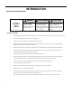

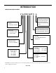
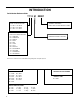
Table Of Contents
- INTRODUCTION
- IMPORTANT SAFETY INFORMATION
- PERSONAL INJURY OR DEATH HAZARDS
- Operation of Equipment in During Construction
- Equipment Identification
- Model and Serial Number Location
- Model and Serial Number information is found on the Manufacturer’s DATA TAG, located on the front or top.
- Model Number Reference Guide
- SERIAL NUMBER REFERENCE GUIDE
- Chassis Specifications
- Small Chassis Dimensions
- Large Chassis Dimensions
- Electrical Data
- Electrical Requirements
- Electrical Ratings Table
- Supply Air Flow and Data
- ELECTRONIC CONTROL BOARD FEATURES
- Electronic Sequence of Operation
- Interface Connector Definitions
- Remote Wall Thermostat
- Remote Wall Thermostat Location
- Desk Control
- Auxiliary Fan Control
- Unit Heat Control Operation - Heat Pump With Electric Heat
- Refrigeration Sequence Of Operation
- Remove The Chassis
- Servicing / Chassis Quick Changeouts
- To Remove the Chassis from the Closet:
- Refrigerant Charging
- Undercharged Refrigerant Systems
- Overcharged Refrigerant Systems
- Restricted Refrigerant System
- Sealed System Method of Charging/ Repairs
- Checking External Static Pressure
- Explanation of charts
- Indoor Airflow Data
- Ductwork Preparation
- Fresh Air Door
- Checking Approximate Airflow
- Electric Heat Strips
- COMPONENT TESTING
- Hermetic Components Check
- Reversing Valve Description And Operation
- Testing The Reversing Valve Solenoid Coil
- Checking The Reversing Valve
- Touch Test Chart : To Service Reversing Valves
- Compressor Checks
- Compressor Replacement -Special Procedure in Case of Compressor Burnout
- Fan Motor
- Capacitors
- Heating Element and Limit Switch
- Drain Pan Valve
- Thermistor Resistence Values (This Table Applies to All Thermistors)
- Testing the Diagnostic Service Module
- Testing the Electronic Control Board
- ELECTRONIC CONTROL BOARD COMPONENTS IDENTIFICATION AND TESTING
- Error Codes and Alarm Status
- Electrical Troubleshooting Chart - Cooling
- 9K Btu, 12K Btu, & 18K Btu
- 24K Btu
- Electrical Troubleshooting Chart - Heat Pump
- Troubleshooting Chart - Cooling
- 9-18K VEA 208/230V
- 9-18K VHA 208/230V
- 9-18K VHA 265V
- 24K VEA 208/230V 2.5/3.4/5.0
- 24K VEA 208/230V 7.5/10.0
- 24K VHA 208/230V 2.5/3.4/5.0
- 24K VHA 208/230V 7.5/10
- 24K VHA 265V 2.5/3.4/5.0
- 24K VHA 265V 7.5/10.0
- VEA9K, VHA9K, VEA12K, VHA12K, VEA18K Figure 901
- AVAILABLE ACCESSORIES
- Thermostat - Rt6
- Thermostat - Rt6p
- Thermostat - WRT1
- Drain Pan

2 PB
Table of Contents
INTRODUCTION 4
Important Safety Information 4
Personal Injury Or Death Hazards 5
Operation of Equipment in During Construction 7
Equipment Identication 8
Model and Serial Number Location 8
Model and Serial Number information is found on the Manufacturer’s DATA TAG, located on the front or top. 8
Model Number Reference Guide 9
Serial Number Reference Guide 10
SPECIFICATIONS 11
Chassis Specications 11
Small Chassis Dimensions 11
Large Chassis Dimensions 12
Electrical Data 13
Electrical Requirements 16
Electrical Ratings Table 16
Supply Air Flow and Data 17
OPERATION 19
Electronic Control Board Features 19
Electronic Sequence of Operation 20
Interface Connector Denitions 21
Remote Wall Thermostat 22
Remote Wall Thermostat Location 23
Desk Control 23
Auxiliary Fan Control 23
Unit Heat Control Operation - Heat Pump With Electric Heat 24
Refrigeration Sequence Of Operation 25
REMOVE AND INSTALL THE CHASSIS 27
Remove The Chassis 27
Servicing / Chassis Quick Changeouts 27
To Remove the Chassis from the Closet: 27
R-410A SEALED SYSTEM REPAIR 28
Refrigerant Charging 29
Undercharged Refrigerant Systems 30
Overcharged Refrigerant Systems 31
Restricted Refrigerant System 32
Sealed System Method of Charging/ Repairs 33
EXTERNAL STATIC PRESSURE 34
Checking External Static Pressure 34
Explanation of charts 35
Indoor Airow Data 35
Ductwork Preparation 35
Fresh Air Door 36
Checking Approximate Airow 36
Electric Heat Strips 36
COMPONENT TESTING 37
Hermetic Components Check 37
Reversing Valve Description And Operation 38
Testing The Reversing Valve Solenoid Coil 39
Checking The Reversing Valve 40
Touch Test Chart : To Service Reversing Valves 42
Compressor Checks 43
Compressor Replacement -Special Procedure in Case of Compressor Burnout 46
Fan Motor 47
Capacitors 47
Heating Element and Limit Switch 48
Drain Pan Valve 50
Thermistor Resistence Values (This Table Applies to All Thermistors) 51
Testing the Diagnostic Service Module 52
Testing the Electronic Control Board 52