
Service and Parts Manual (2016, 2017, 2018, 2014, 2015, 2013, 2012)


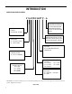
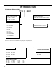
Table Of Contents
- INTRODUCTION
- IMPORTANT SAFETY INFORMATION
- PERSONAL INJURY OR DEATH HAZARDS
- Operation of Equipment in During Construction
- Equipment Identification
- Model and Serial Number Location
- Model and Serial Number information is found on the Manufacturer’s DATA TAG, located on the front or top.
- Model Number Reference Guide
- SERIAL NUMBER REFERENCE GUIDE
- Chassis Specifications
- Small Chassis Dimensions
- Large Chassis Dimensions
- Electrical Data
- Electrical Requirements
- Electrical Ratings Table
- Supply Air Flow and Data
- ELECTRONIC CONTROL BOARD FEATURES
- Electronic Sequence of Operation
- Interface Connector Definitions
- Remote Wall Thermostat
- Remote Wall Thermostat Location
- Desk Control
- Auxiliary Fan Control
- Unit Heat Control Operation - Heat Pump With Electric Heat
- Refrigeration Sequence Of Operation
- Remove The Chassis
- Servicing / Chassis Quick Changeouts
- To Remove the Chassis from the Closet:
- Refrigerant Charging
- Undercharged Refrigerant Systems
- Overcharged Refrigerant Systems
- Restricted Refrigerant System
- Sealed System Method of Charging/ Repairs
- Checking External Static Pressure
- Explanation of charts
- Indoor Airflow Data
- Ductwork Preparation
- Fresh Air Door
- Checking Approximate Airflow
- Electric Heat Strips
- COMPONENT TESTING
- Hermetic Components Check
- Reversing Valve Description And Operation
- Testing The Reversing Valve Solenoid Coil
- Checking The Reversing Valve
- Touch Test Chart : To Service Reversing Valves
- Compressor Checks
- Compressor Replacement -Special Procedure in Case of Compressor Burnout
- Fan Motor
- Capacitors
- Heating Element and Limit Switch
- Drain Pan Valve
- Thermistor Resistence Values (This Table Applies to All Thermistors)
- Testing the Diagnostic Service Module
- Testing the Electronic Control Board
- ELECTRONIC CONTROL BOARD COMPONENTS IDENTIFICATION AND TESTING
- Error Codes and Alarm Status
- Electrical Troubleshooting Chart - Cooling
- 9K Btu, 12K Btu, & 18K Btu
- 24K Btu
- Electrical Troubleshooting Chart - Heat Pump
- Troubleshooting Chart - Cooling
- 9-18K VEA 208/230V
- 9-18K VHA 208/230V
- 9-18K VHA 265V
- 24K VEA 208/230V 2.5/3.4/5.0
- 24K VEA 208/230V 7.5/10.0
- 24K VHA 208/230V 2.5/3.4/5.0
- 24K VHA 208/230V 7.5/10
- 24K VHA 265V 2.5/3.4/5.0
- 24K VHA 265V 7.5/10.0
- VEA9K, VHA9K, VEA12K, VHA12K, VEA18K Figure 901
- AVAILABLE ACCESSORIES
- Thermostat - Rt6
- Thermostat - Rt6p
- Thermostat - WRT1
- Drain Pan

4 PB
Your safety and the safety of others is very
important.
We have provided many important safety messages in this manual and on your appliance. Always read and obey all
safety messages.
This is a safety Alert symbol.
This symbol alerts you to potential hazards that can kill or hurt you and others.
All safety messages will follow the safety alert symbol with the word “WARNING”
or “CAUTION”. These words mean:
Indicates a hazard which, if not avoided, can result in severe personal injury or death
and damage to product or other property.
Indicates a hazard which, if not avoided, can result in personal injury and damage to
product or other property.
All safety messages will tell you what the potential hazard is, tell you how to reduce
the chance of injury, and tell you what will happen if the instructions are not fol-
lowed.
Indicates property damage can occur if instructions are not followed.
WARNING
Refrigeration system
under high pressure
Do not puncture, heat, expose to ame or incinerate.
Only certied refrigeration technicians should service
this equipment.
R410A systems operate at higher pressures than R22
equipment. Appropriate safe service and handling
practices must be used.
Only use gauge sets designed for use with R410A.
Do not use standard R22 gauge sets.
NOTICE
CAUTION
WARNING
The information in this manual is intended for use by a qualied technician who is familiar with the safety procedures
required for installation and repair, and who is equipped with the proper tools and test instruments required to
service this product.
Installation or repairs made by unqualied persons can result in subjecting the unqualied person making such
repairs as well as the persons being served by the equipment to hazards resulting in injury or electrical shock
which can be serious or even fatal.
Safety warnings have been placed throughout this manual to alert you to potential hazards that may be encountered.
If you install or perform service on equipment, it is your responsibility to read and obey these warnings to guard
against any bodily injury or property damage which may result to you or others.
Important Safety Information
INTRODUCTION