
Service and Parts Manual (2016, 2017, 2018, 2014, 2015, 2013, 2012)
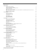
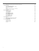

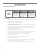

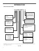
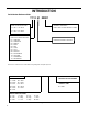
Table Of Contents
- INTRODUCTION
- IMPORTANT SAFETY INFORMATION
- PERSONAL INJURY OR DEATH HAZARDS
- Operation of Equipment in During Construction
- Equipment Identification
- Model and Serial Number Location
- Model and Serial Number information is found on the Manufacturer’s DATA TAG, located on the front or top.
- Model Number Reference Guide
- SERIAL NUMBER REFERENCE GUIDE
- Chassis Specifications
- Small Chassis Dimensions
- Large Chassis Dimensions
- Electrical Data
- Electrical Requirements
- Electrical Ratings Table
- Supply Air Flow and Data
- ELECTRONIC CONTROL BOARD FEATURES
- Electronic Sequence of Operation
- Interface Connector Definitions
- Remote Wall Thermostat
- Remote Wall Thermostat Location
- Desk Control
- Auxiliary Fan Control
- Unit Heat Control Operation - Heat Pump With Electric Heat
- Refrigeration Sequence Of Operation
- Remove The Chassis
- Servicing / Chassis Quick Changeouts
- To Remove the Chassis from the Closet:
- Refrigerant Charging
- Undercharged Refrigerant Systems
- Overcharged Refrigerant Systems
- Restricted Refrigerant System
- Sealed System Method of Charging/ Repairs
- Checking External Static Pressure
- Explanation of charts
- Indoor Airflow Data
- Ductwork Preparation
- Fresh Air Door
- Checking Approximate Airflow
- Electric Heat Strips
- COMPONENT TESTING
- Hermetic Components Check
- Reversing Valve Description And Operation
- Testing The Reversing Valve Solenoid Coil
- Checking The Reversing Valve
- Touch Test Chart : To Service Reversing Valves
- Compressor Checks
- Compressor Replacement -Special Procedure in Case of Compressor Burnout
- Fan Motor
- Capacitors
- Heating Element and Limit Switch
- Drain Pan Valve
- Thermistor Resistence Values (This Table Applies to All Thermistors)
- Testing the Diagnostic Service Module
- Testing the Electronic Control Board
- ELECTRONIC CONTROL BOARD COMPONENTS IDENTIFICATION AND TESTING
- Error Codes and Alarm Status
- Electrical Troubleshooting Chart - Cooling
- 9K Btu, 12K Btu, & 18K Btu
- 24K Btu
- Electrical Troubleshooting Chart - Heat Pump
- Troubleshooting Chart - Cooling
- 9-18K VEA 208/230V
- 9-18K VHA 208/230V
- 9-18K VHA 265V
- 24K VEA 208/230V 2.5/3.4/5.0
- 24K VEA 208/230V 7.5/10.0
- 24K VHA 208/230V 2.5/3.4/5.0
- 24K VHA 208/230V 7.5/10
- 24K VHA 265V 2.5/3.4/5.0
- 24K VHA 265V 7.5/10.0
- VEA9K, VHA9K, VEA12K, VHA12K, VEA18K Figure 901
- AVAILABLE ACCESSORIES
- Thermostat - Rt6
- Thermostat - Rt6p
- Thermostat - WRT1
- Drain Pan

9 PB
INTRODUCTION
Model Number Reference Guide
SERIES
V=VERTICAL SERIES
FUNCTION
E - ELECTRIC HEAT
H - HEAT PUMP
DESIGN SERIES
A = 32”/47” CABINET
NOMINAL CAPACITY
A SERIES (Btu/h)
09= 9,000
12 = 12,000
18 = 18,000
24 = 24,000
ENGINEERING REVSION
LETTER INDICATES AN
ENGINEERING MODIFI-
CATION TO AN EXISTING
MODEL
MARKETING SUFFIX LETTER
INDICATES MODIFICATION TO
AN EXISTING MODEL SERIES
OPTIONS
RT = STANDARD REMOTE
OPERATION
ELECTRIC HEATER SIZE
A SERIES
25 = 2.5 KW 75 = 7.5KW
34 = 3.4 KW 10 = 10KW
50 = 5.0 KW
VOLTAGE
K = 208/230V - 1PH-60Hz
R = 265V
IMPORTANT: It will be necessary for you to accurately identify the unit you are servicing, so you can be certain of a
proper diagnosis and repair.
Figure 103
V E A 09 K 34 RT P - A