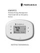
EMWRT2 Wireless Energy Management Thermostat with an Occupancy Sensor INSTRUCTION MANUAL
Table of Contents Introduction............................................................................................................. 5 Thermostat Installation........................................................................................... 8 Pairing the Thermostat and the Control Card......................................................... 8 Installing the Wireless Control Card....................................................................... 9 Mounting the thermostat to the wall.....
Table of Contents 18 – MAXIMUM SET POINT................................................................................ 38 19 – TEMPERATURE CONTROL MODE............................................................ 39 20 – AUTO CHANGEOVER SET POINT OFFSET (DEAD BAND)...................... 40 21 – SETBACK SET POINTS / AUTO-RESTORE............................................... 41 22 – AUTOMATIC HUMIDITY CONTROL†........................................................... 42 23 – TEMPERATURE CALIBRATION........
Introduction Friedrich EMWRT2 Energy Management Thermostats for the hospitality industry deliver unprecedented energy savings without compromising guest comfort. An integrated occupancy sensor uses a combination of motion and thermal sensing technologies for accurate occupancy detection. Reliable occupancy detection allows saving energy when rooms are unoccupied. Energy saving presets eliminate the guesswork and make it easy to adjust the energy saving settings.
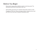
Before You Begin ➤➤ Determine the appropriate installation location for the thermostat. The thermostat should face the bed area of the room. ➤➤ Set the PTAC/ Vert-I-Pak unit to “External Thermostat” (Class 2) mode. Consult the PTAC/ Vert-I-Pak unit documentation to determine how to set the PTAC/ Vert-I-Pak unit to “External Thermostat” mode.
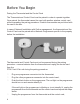
Before You Begin Pairing the Thermostat and the Control Card The Thermostat and Control Card must be paired in order to operate together. Once paired, the thermostat cannot be used with another wireless control card without repeating the pairing procedure. Friedrich thermostats are pre-linked with the card in the box. In case of Network Installation with Online management, the thermostat and the Control Card must be paired with a Network Programmer specific to the property before the installation.
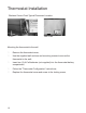
Thermostat Installation Installing the Wireless Control Card ➤➤ Unplug the PTAC/ Vert-I-Pak* unit from power supply ➤➤ Connect the low voltage wires to screw terminals on the PTAC/ Vert-I-Pak* unit low voltage terminal block - refer to the Wiring Table to determine proper connections. ➤➤ Mount the control card to the PTAC/ Vert-I-Pak* unit. Ensure that the Wireless Control Card antenna is not touching any metal components of the PTAC/ Vert-I-Pak* unit.
Thermostat Installation Wireless Control Card-Typical Placement Location PTAC Vert-I-Pak Mounting the thermostat to the wall ➤➤ Remove the thermostat cover; ➤➤ Use the supplied wall anchors and mounting screws to secure the thermostat to the wall; ➤➤ Insert two (2) A-Cell batteries (not-supplied) into the thermostat battery compartment; ➤➤ Follow the “Thermostat Configuration” instructions; ➤➤ Replace the thermostat cover and screw in the locking screw; 10
Thermostat Configuration Once the thermostat is powered, thermostat configuration settings will appear on the thermostat screen. In order to properly operate the PTAC/Vert-I-Pak unit: ➤➤ Set the thermostat clock; ➤➤ Enter the room number; ➤➤ Configure the equipment settings; ➤➤ Select Energy Savings Preset; The thermostat configuration screens have a 3-minute time-out. If no action is taken within three (3) minutes, the thermostat will exit configuration settings.
Thermostat Configuration Setting the thermostat clock HOURS MINUTES Set the thermostat clock to current time in 24h (Military Time) format. ➤➤ Use the “Up” and “Down” buttons to set the hours; ➤➤ Press the “Fan” button to advance to the minutes setting; ➤➤ Use the “Up” an “Down” buttons to set the minutes; ➤➤ Press the “F/C” button to advance to the next menu; Setting the clock correctly is crucial for proper operation of the thermostat.
Thermostat Configuration Entering the room number Enter the room number by changing the digits on the screen. Leading zeros “0” preceding other digits will be ignored, i.e. Room number “123” should be entered as “00123”. ➤➤ Use the “Up” and “Down” buttons to change the digit; ➤➤ Press the “Fan” button advance to the next digit; ➤➤ Press the “F/C” button to advance to the next menu; Entering the room number correctly is crucial for proper operation of remotely managed thermostats.
Thermostat Configuration Configuring the Equipment Settings - Compressor Type COMPRESSOR TYPE ➤➤ 0 1 2* ➤➤ * 14 Use the “Up” and “Down” buttons to change the compressor type by changing the first digit; No Compressor Heat Pump Air Conditioner Press the “Fan” button to advance to the next setting; Indicates default setting;
Thermostat Configuration Configuring the Equipment Settings - Electric Heat ELECTRIC HEAT ➤➤ Use the “Up” and “Down” buttons to change the Electric Heat setting by changing the second digit; 0 1* ➤➤ * No Electric Heat Electric Heat Press the “Fan” button to advance to the next setting; Indicates default setting; 15
Thermostat Configuration Configuring the Equipment Settings - Reversing Valve REVERSING VALVE ➤➤ Use the “Up” and “Down” buttons to change the Reversing Valve setting by changing the third digit; 0 1* OB contact is energized to cool; OB contact is energized to heat; Refer to the HVAC unit documentation to determine the correct OB VALVE setting.
Thermostat Configuration Configuring the Energy Saving Settings ➤➤ Use the “Up” and “Down” buttons to select the Energy Saving preset: E-0* E-1 E-2 E-3 E-4 E-5 E-C Energy Savings Off - No Temperature Setback; Lowest Energy Savings; Lower Energy Savings; Standard Energy Savings; Higher Energy Savings; Highest Energy Savings; Refer to the APPENDIX 1 for Energy Saving Preset details.
Thermostat Configuration Testing the thermostat Following the thermostat configuration, test if the thermostat is controlling the HVAC unit. ➤➤ Press the “Power” button to turn the thermostat ON; ➤➤ Press the “Up” and “Down” buttons to change the temperature set point above and below the current room temperature to test if the thermostat initiates heating and cooling - the HVAC unit should turn heating and air conditioning on and off.
Custom Energy Savings Settings If you don’t want to use the one of the energy saving presets detailed in the Appendix 1, you can enter the custom energy savings settings. Accessing the Thermostat Settings ➤➤ Press and hold the “Configuration” button until the first thermostat settings screen appears. The thermostat must be turned on to access the thermostat settings.
Custom Energy Savings Settings Using the Thermostat Settings Screens SETTING VALUE SCREEN NUMBER ➤➤ Use the “Up” and “Down” buttons to change the setting; ➤➤ Press the “F/C” button to advance to the next setting; ➤➤ Press the “Fan” button to return to the previous setting; ➤➤ Press the “Power” button to save and exit thermostat settings; 20
Custom Energy Savings Settings 01 – FAN CONTROL MODE Select Fan Control Mode: 00 01 * * MANUAL - guest can select automatic or continuous fan mode; AUTOMATIC - fan runs only when there is a demand for heating or air conditioning; Indicates default setting; 21
Custom Energy Savings Settings 02 – 1ST STAGE DIFFERENTIAL - HEAT 02-30 22 (0.2°F - 3.0°F; 0.5°F* default setting) Select the number of degrees the thermostat has to sense between the automatic changeover temperature for heat and the room temperature before a call for the 1st stage heating is initiated.
Custom Energy Savings Settings 03 – 2ND STAGE DIFFERENTIAL - HEAT 10-20 (1.0°F - 2.0°F*; 2.0°F* default setting) Select the difference between 1st stage heating and 2nd stage heating initiation.
Custom Energy Savings Settings 04 – 1ST STAGE DIFFERENTIAL - COOL 02-30 24 (0.2°F - 3.0°F; 0.5°F* default setting) Select the number of degrees the thermostat has to sense between the automatic changeover temperature for cool and the room temperature before a call for the 1st stage cooling is initiated.
Custom Energy Savings Settings 05 – INCIDENTAL OCCUPANCY THRESHOLD 00-60 (05* default setting) Select the minimum period of time (in minutes) for which occupancy needs to be detected to enter the guest occupancy mode. When occupancy is detected, thermostat will switch to occupied mode for a duration of “Incidental Occupancy Threshold” selected here.
Custom Energy Savings Settings 06 – NIGHT OCCUPANCY THRESHOLD 00-60 (01* default setting) Select the minimum period of time (in minutes) for which occupancy needs to be detected in order to consider the room occupied during the “Night Occupancy”period. When occupancy is detected during the “Night Occupancy Period” for longer than the “Night Occupancy Threshold” selected here, the thermostat will instantaneously switch to occupied mode.
Custom Energy Savings Settings 07 – FORCED 2ND STAGE HEATING 00-60 (30* default setting) Select a number of minutes 1st stage heating will run before 2nd stage heating is automatically initiated if the guest set point is not reached and the 2nd stage heating is not initiated through differential settings. This feature allows automatically turning on 2nd stage heating to avoid excessive compressor use. Set to 00 to disable the feature.
Custom Energy Savings Settings 08 – NIGHT OCCUPANCY START 00-23 (21* default setting) Select the start time (in hours - 24hour clock) for “Night Occupancy” If occupancy is detected for a period of time longer than the “Night Occupancy Threshold” during “Night Occupancy” period, the thermostat will disable the occupancy sensor and consider the room occupied until the end of the “Night Occupancy” period.
Custom Energy Savings Settings 09 – NIGHT OCCUPANCY END 00-23 (09* default setting) Select the time (in hours - 24-hour clock) for “Night Occupancy” to end. The time of day the “Night Occupancy” ends and the thermostat switches back to the room sensing settings chosen in the other occupancy modes.
Custom Energy Savings Settings 10 – TEMPERATURE RECOVERY TIME 00-60 (25* default setting) Select the maximum time allowed for a HVAC unit to attain temperature as defined by Heat and Cool “Recovery Temperature”; “Temperature Recovery Time” selected here and the actual temperature recovery ability of the HVAC unit are used to calculate setback temperatures.
Custom Energy Savings Settings 11 – RECOVERY TEMPERATURE - HEAT 62-82 (67°F* default setting) Select the room temperature in °F that a HVAC unit will have to attain within the selected “Temperature Recovery Time” when there is a need for heating.
Custom Energy Savings Settings 12 – TEMPERATURE SETBACK DELAY - HEAT 00-120 (20* default setting) Select the time delay (in minutes) for which the room that is in the guest occupancy mode needs to be unoccupied before the temperature setback is initiated. This feature prevents initiating temperature setback prematurely while the guest is still in the room but in an area where occupancy cannot be detected by the occupancy sensor.
Custom Energy Savings Settings 13 – MINIMUM SETBACK TEMPERATURE 52-72 (64°F* default setting) Select the “Minimum Setback Temperature” in °F. Setback temperature is calculated by measuring HVAC unit’s ability to attain “Recovery Temperature - Heat” within “Temperature Recovery Time”. If recovery is disabled (“Temperature Recovery Time” is set to “0”) or if setback temperatures have not yet been calculated, the “Minimum Setback Temperature” value will be used as the setback temperature for heating.
Custom Energy Savings Settings 14 – TEMPERATURE SETBACK DELAY - COOL 00-120 (20* default setting) Select the time delay (in minutes) for which the room that is in the guest occupancy mode needs to be unoccupied before the temperature setback is initiated. This feature prevents initiating temperature setback prematurely while the guest is still in the room but in an area where occupancy cannot be detected by the occupancy sensor.
Custom Energy Savings Settings 15 – MAXIMUM SETBACK TEMPERATURE 72-92 (78°F* default setting) Select the “Maximum Setback Temperature” in °F. Setback temperature is calculated by measuring HVAC unit’s ability to attain “Recovery Temperature - Cool” within “Temperature Recovery Time”. If recovery is disabled (“Temperature Recovery Time” is set to “0”) or if setback temperatures have not yet been calculated, the “Maximum Setback Temperature” value will be used as the setback temperature for cooling.
Custom Energy Savings Settings 16 – RECOVERY TEMPERATURE - COOL 62-82 36 (74°F* default setting) Select the room temperature in °F that a HVAC unit will have to attain within the selected “Temperature Recovery Time” when there is a need for air conditioning.
Custom Energy Savings Settings 17 – MINIMUM SET POINT 64-84 (66°F* default setting) Select the minimum set point in °F that a guest can select.
Custom Energy Savings Settings 18 – MAXIMUM SET POINT 60-82 38 (78°F* default setting) Select the maximum set point in °F that a guest can select.
Custom Energy Savings Settings 19 – TEMPERATURE CONTROL MODE Select Temperature Control Mode: 00 01 * * MANUAL - Allows users to select HEAT only or COOL only temperature control mode to maintain the room temperature; AUTOMATIC - Thermostat automatically turns on heating or air conditioning to maintain the room temperature at the selected temperature set point; Indicates default setting; 39
Custom Energy Savings Settings 20 – AUTO CHANGEOVER SET POINT OFFSET (DEAD BAND) 00-04 (01°F* default setting) Select the difference between the guest-selected set point and the heat and the cool set point when the thermostat is in the automatic temperature control mode. This value plus the 1st stage differential defined in steps 02 and 04, defines the temperature at which the thermostat would automatically change heating/cooling modes. .
Custom Energy Savings Settings 21 – SETBACK SET POINTS / AUTO-RESTORE 00 01 02 03 * When room is unoccupied and the thermostat is in the setback mode or turned off, it will NOT maintain the temperature between heat and cool setback set points; When guest enters the room, the thermostat will be turned off - it will not automatically restore the most recent guest settings; When room is unoccupied and the thermostat is in the setback mode or turned off, it will maintain the temperature between heat and co
Custom Energy Savings Settings 22 – AUTOMATIC HUMIDITY CONTROL† 00 01 * Disable automatic humidity control; Enable automatic humidity control; When “Automatic Humidity Control” is enabled, thermostat will turn on air conditioning in an unoccupied room when humidity raises above 60% and room temperature is above 72°F until either room humidity is below 55% or room temperature is below 72°F; * Indicates default setting; † This setting is active only on thermostats with enabled humidity features.
Custom Energy Savings Settings 23 – TEMPERATURE CALIBRATION -5.0 – 5.0 (0.0°F* default setting) Calibrate the temperature display : -5.0°F - 5.0°F.
Thermostat Maintenance Replacing Thermostat Batteries The low battery indicator will be displayed on the thermostat screen when it is necessary to replace batteries in the thermostat. Under normal operating conditions, new brand-name alkaline batteries will last for a period of approximately one (1) year. Please replace batteries every twelve (12) months to ensure continuous thermostat operation.
Troubleshooting Error Codes ERR 1 Thermostat Temperature Sensor Hardware Defect ERR 2 Thermostat Radio Hardware Defect ERR 3 Thermostat Radio Software Defect ERR 4 No link with the Wireless Control Card ERR 5 Thermostat Memory Defect 45
Troubleshooting Thermostat is not controlling the PTAC/Vert-I-Pak unit. Verify the status of the red light on the Wireless Control Card; ➤➤ The red light is off The Wireless Control Card is not powered.
SCREEN NUMBER APPENDIX 1 - Energy Saving Presets Level 0 Level 1 Level 2 Level 3 Level 4 Level 5 19 Temperature Control Mode AUTO AUTO AUTO AUTO AUTO AUTO 01 Fan Control Mode AUTO AUTO AUTO AUTO AUTO AUTO 17 Minimum Setpoint 64 64 65 66 67 68 18 Maximum Setpoint 82 82 80 78 76 74 20 Deadband 2 2 2 2 2 2 02 1st Stage Differential Heat 0.5 0.5 0.5 0.5 0.5 0.5 03 2nd Stage Differential Heat 1 1 1 2 2 2 04 1st Stage Differential Cool 0.5 0.5 0.5 0.5 0.
APPENDIX 2 - Glossary “Automatic Fan Control Mode” - fan runs only when there is a demand for heating or cooling; be detected in order to enter the “Guest Occupancy” mode; “Manual Fan Control Mode” - guest can select automatic or continuous fan operation; “Night Occupancy Threshold” - the minimum period of time during the “Night Occupancy” period for which occupancy needs to be detected in order to enter the “Night Occupancy” mode; “Minimum Set point” - minimum temperature that a guest can request; “Max
Technical Specifications Case Dimensions (Imperial) Case Dimensions (Metric) Screen Dimensions (Imperial) Screen Dimensions (Metric) Operating Voltage Thermostat Wireless Control Card 4.015 x 5.5118” x 0.925” 3.875” x 2.125” x 0.75” 102mm x 140mm x 23.5mm 98mm x 54mm x 19mm 3.625" x 2.
Friedrich Air Conditioning Co. 10001 Reunion Place, Ste 500 San Antonio, TX 78216 (210) 546-0500 / (800) 541-6645 www.friedrich.