
Accessory EMWRT2 Manual (2020)


9
Thermostat Installation
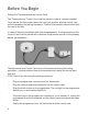
Installing the Wireless Control Card
➤ Unplug the PTAC/Vert-I-Pak* unit from power supply
➤ Connect the low voltage wires to screw terminals on the PTAC/Vert-I-Pak*
unit low voltage terminal block - refer to the Wiring Table to determine
proper connections.
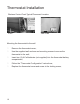
➤ Mount the control card to the PTAC/Vert-I-Pak* unit.
Ensure that the Wireless Control Card antenna is not touching any metal
components of the PTAC/Vert-I-Pak* unit.
Ensure that the Wireless Control Card Antenna is facing the thermostat on
the wall and is oriented so that any metal parts of the PTAC/ Vert-I-Pak* unit
do not obstruct the wireless communication to the thermostat and, in case
of a network installation, to other wireless control cards and the server.
Ensure that the control card is secured and cannot fall into the
PTAC/Vert-I-Pak* unit Condensation Pan.
➤ Plug in the PTAC/Vert-I-Pak* unit to power supply.
NOTE: If the PTAC/Vert-I-Pak* unit has only one (1) fan speed, connect both fan
control wires – Green and Purple – to the fan terminal (G).
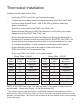
Wiring Table - 24V AC
Wire
Color
Terminal
Letter
Terminal
Connection
Black C Common
Red R 24V
Yellow Y Compressor
White W Heat
Orange O or B Reverse Valve
Green GH Fan High
Purple GL Fan Low
Wiring Table - 24V DC
Wire
Color
Terminal
Letter
Terminal
Connection
Black R 24V
Red C Common
Yellow Y Compressor
White W Heat
Orange O or B Reverse Valve
Green GH Fan High
Purple GL Fan Low
* The wireless control card should never be installed inside the metal electrical control
enclosure/box of the PTAC/Vert-I-Pak unit. Failure to comply will result in obstruction to the
wireless communication. The control card is always to be mounted as shown on the pictures
on the next page.