Service/ Parts Manual Thru - the Wall Air Conditioners Wallmaster Models Cool Only 115-Volt: WCT08A10A, WCT10A10A, WCT12A10A, WCT12A10B 230-Volt: WCT10A30A, WCT12A30A, WCT16A30A Electric Heat 230-Volt: WET10A33A, WET12A33A, WET16A33A Heat Pump 230-Volt: 1 93001405_02 WHT12A33A
Table of Contents INTRODUCTION 3 Important Safety Information 3 Personal Injury Or Death Hazards 4 New Wallmaster Control Options 6 Model and Serial Number Location 7 Model Number Reference Guide 8 Serial Number Reference Guide 9 SPECIFICATIONS 10 Refrigeration Systems Performance Data 10 Electrical Data 12 Circuit Rating/ Breaker/ power cord/ wall Receptacle 12 OPERATION 14 Airflow Adjustment 14 User Interface 15 Wi-Fi Set Up Instructions 27 Control Panel 31 Remote Control 32 Unit 33 Refriger
INTRODUCTION Important Safety Information The information in this manual is intended for use by a qualified technician who is familiar with the safety procedures required for installation and repair, and who is equipped with the proper tools and test instruments required to service this product.
INTRODUCTION Personal Injury Or Death Hazards WARNING SAFETY FIRST Do not remove, disable or bypass this unit’s safety devices. Doing so may cause fire, Doing so may cause fire, injuries, or death. AVERTISSEMENT Ne pas supprime, désactiver ou contourner cette l´unité des dispositifs de sécurité, faire vous risqueriez de provoquer le feu, les blessures ou la mort. ADVERTENCIA No eliminar, desactivar o pasar por alto los dispositivos de seguridad de la unidad.
INTRODUCTION PERSONAL INJURY OR DEATH HAZARDS 5 • REFRIGERATION SYSTEM REPAIR HAZARDS: • Use approved standard refrigerant recovering procedures and equipment to relieve high pressure before opening system for repair. • Do not allow liquid refrigerant to contact skin. Direct contact with liquid refrigerant can result in minor to moderate injury. • Be extremely careful when using an oxy-acetylene torch. Direct contact with the torch’s flame or hot surfaces can cause serious burns.
INTRODUCTION New Wallmaster Control Options The new Wallmaster gives you a variety of options for control, programming, and scheduling including wireless capabilities. Wireless Programming and Control: Friedrich Connect allows you to conveniently control, program, and monitor your air conditioning unit remotely from a smartphone or computer. Pre-Programmed Timer Options: Your unit’s digital control comes equipped with a 24-hour timer.
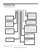
INTRODUCTION This service manual is designed to be used in conjunction with the installation and operation manuals provided with each air conditioning system. This service manual was written to assist the professional service technician to quickly and accurately diagnose and repair malfunctions. Installation procedures are not given in this manual. They are given in the Installation/Operation manual which can be aquired on the Friedrich website.
INTRODUCTION Model Number Reference Guide K C M 21 A 3 0 A - A MODEL TYPE K - KUHL W - WALLMASTER FUNCTION C - COOL ONLY E - ELECTRIC HEAT H - HEAT PUMP APPLICATION T - THRU THE WALL ENGINEERING REVSION LETTER INDICATES AN ENGINEERING MODIFICATION TO AN EXISTING MODEL MARKETING SUFFIX LETTER INDICATES MODIFICATION TO AN EXISTING MODEL HEAT STRIP 0 - STRAIGHT COOL & HEAT PUMP 3 -3.3 KW HEAT STRIP, NOMINAL 4 - 4.0 KW HEAT STRIP, NOMINAL 5 - 5.
INTRODUCTION Serial Number Reference Guide 17 12 M 00001 YEAR OF MANUFACTURE 17 = 2017 18 = 2018 19 = 2019 20 = 2020 21 = 2021 22 = 2022 MONTH OF MANUFACTURE 01 = JANUARY 02 = FEBRUARY 03 = MARCH 04 = APRIL 05 = MAY 06 = JUNE 07 = JULY 08 = AUGUST 09 = SEPTEMBER 10 = OCTOBER 11 = NOVEMBER 12 = DECEMBER NUMERIC SEQUENCE FIRST UNIT OF EACH MONTH = 00001 FACTORY DESIGNATION M = FRIEDRICH MTY Figure 104 (Serial Number Reference Guide) 9
SPECIFICATIONS Refrigeration Systems Performance Data Electrical Ratings Model Condensor Temp Deg F. Discharge Suction Temp Temp Deg. F Deg F AMPS COOL AMPS HEAT R-410A REF. LOCKED ROTOR CHARGE AMPS IN OZ Breaker Voltage 60 HERTZ AMPS Cool Only WCT08A10A 121 161 64 7 30.5 23.5 115 15 WCT10A10A 125 158 50 9.3 49 26.6 115 15 WCT10A30A 122 162 53 4.4 21 24 230 15 WCT12A10A 121 159 55 11.1 52 32.5 115 15 WCT12A10B 121 159 55 10.5 52 27.
SPECIFICATIONS Model UPC Cooling Btu Heating Btu Volts Cooling Amps Cooling Watts Heating Heating Amps Watts 7.0 748 — — Moisture RemovalCOP Pints/HR CFM EER CEER — 10.7 10.6 — 1.8 250 — 10.7 10.6 — 2.4 250 9.5 — 3.8 295 Cooling Only WCT08A10A 724587436655 8000 — 115 WCT10A10A 724587436662 10000 — 115 9.3 935 WCT12A10A 724587436952 12000 — 115 11.1 1250 — — 9.6 WCT12A10B 724587436952 11600 — 115 10.5 11700 — — 9.6 9.5 — 3.
SPECIFICATIONS Electrical Data WARNING NOTICE ELECTRIC SHOCK HAZARD Turn off electric power before service or installation. All electrical connections and wiring MUST be the National Electrical Code and all local codes which have jurisdiction. Failure to do so can result in personal injury or death. FIRE HAZARD electically unsafe conditions which could cause moderate or serious property damage. Read, understand and follow the above warning.
SPECIFICATIONS Electrical Data WARNING RESET Electrical Shock Hazard Make sure your electrical receptacle has the same configuration as your air conditioner’s plug. If different, consult a Licensed Electrician. Do not use plug adapters. Do not use an extension cord. Do not remove ground prong.Always plug into a grounded 3 prong outlet. Failure to follow these instructions can result in death, fire, or electrical shock. TEST WARNING: TEST BEFORE EACH USE! 1. PRESS REST BUTTON. 2.
OPERATION Airflow Adjustment The airflow path may be adjusted to distribute air independently from the left or right side of the discharge opening. Each of the banks of louvers can be directed left, right, up, or down in order to achieve the most optimum airflow positioning. To adjust airflow direction left or right, grab the lever in the center of the louver bank and move it in the direction that you would like the air to be directed.
OPERATION User Interface All of the control panel function buttons and mode icons can be viewed in Figures 302. Power On – Press the button to turn on the air conditioner. The power button illuminates to indicate that the power is on. The backlight on the power switch will automatically turn off after 20 seconds of inactivity. The remote control can also be used to turn power ON / OFF (see Remote Control). Display – The display is a high efficiency LCD with a built-in backlight.
OPERATION User Interface Accessing Sub-Menus The MENU button accesses the sub-menu. See Figure 10. Press the Menu Button to enter the Menu. See Figure 303. The arrow buttons navigate the 6 menu options. See Figure 304. – LIM – LOCK – TM – CnCT – F-C – diAG The return button exits the menu. See Figure 304.
OPERATION User Interface Navigating Inside the Sub-Menus The MENU button moves you forward through the sub-menu. See Figure 306. The return button moves you backward once inside the LIM, TM, F-C, LOCK, CnCt, and diag menus. See Figure 306.
OPERATION User Interface The LIM Menu (LIMIT) This is the limit menu. See Figure 307. Upon entering the menu, the first option will be to set the lower setpoint limit using the arrow buttons. See Figure 308. Then you can set the higher setpoint limit using the arrow buttons. See Figure 309. Pressing the menu button completes the limit setting. See Figure 306.
OPERATION User Interface The TM Menu (Timer) This is the TM menu used to set a timer. See Figure 310. In the menu, you set the current time using the arrow buttons. See Figure 311. (Note: These two “set clock” steps will be skipped if the unit is already connected to Wi-Fi.) First, set the hour. Using the MENU button, you switch to the minutes and complete setting the time. See Figure 306. You select your mode. Either cool, heat, or auto. Toggle these using the mode button. See Figure 312.
OPERATION User Interface The TM Menu (Timer) continued Auto mode selected. See Figure 313. Set the cool setpoint for your first timer period using the arrow buttons. The cooling mode timer only sets the cool setpoint. See Figure 314. Next, set the heat setpoint for your first timer period. The heating mode timer only sets the heat setpoint. See Figure 315. Note: The auto mode timer sets both the cool and heat setpoint. Set the time to start the first timer period. See Figure 316.
OPERATION User Interface The TM Menu (Timer) continued Set the cool setpoint for the second scheduled timer. See Figure 317. Set the heat setpoint for the second timer. Set the time to start the second timer period. See Figure 318. Press the MENU button to complete the time timer setup. See Figure 306.
OPERATION User Interface The F-C Menu (Fahrenheit/ Celsius) This menu is used to toggle between Fahrenheit and Celsius. See Figure 319. Using the arrow buttons on the right side switches it from Fahrenheit to Celsius. See Figures 320 and 321.
OPERATION User Interface The Lock Menu This menu is used to lock the settings with a four(4) digit passcode. This is the Lock Menu. See Figure 322. The menu lock is defaulted to off. Use the arrows to toggle between off and on. See Figure 323. This is LOCK on. See Figure 324. Set the first digit of the password using the arrow buttons. Use the menu button to proceed to the next digit. See Figures 306 and 325. Repeat the previous step for the remaining three(3) digits.
OPERATION User Interface The Lock Menu continued The ON on the right side of the display shows the lock function is active. See Figure 326. To go back into the menu, select the menu button again. See Figure 306. Enter the password in the same manner it was created. See Figure 327. Entering the correct password will give the user access to all of the sub-menus. See Figure 328 Accessing the lock menu will allow you to toggle lock OFF if needed.
OPERATION User Interface The diAG Menu This menu is used to access the diagnostic codes. See Figure 330. Selecting this sub-menu shows the E that represents “Error.” See Figure 331. Toggle through the error codes using the arrow keys. See Figure 332.
OPERATION User Interface The CnCT Menu (WiFi Connection) This menu is used to turn on Wi-Fi connection. This is the CnCT menu. See Figure 333 Pressing the menu button will activate Wi-Fi. See Figure 306. To setup WiFi, refer to Wi-Fi setup instructions. The Wi-Fi symbol in the top right corner of the display shows Wi-Fi connection is on. See Figure 334.
OPERATION Wi-Fi Set Up Instructions Below are the set-up instructions for Wi-Fi to use your unit wirelessly. Follow the instructions below: 1. Write down the following information prior to beginning this process (If you do not know this information you can check your router or contact your internet provider) a. WI-FI Network Name (SSID)__________________________ b. WI-FI Network Security Type (Open, wep, wpa, wpa2) _________ c. WI-FI Network Password ___________________________ 2.
OPERATION Wi-Fi SET UP INSTRUCTIONS (CONT) 6. To start the setup process click the menu button on the Control Panel of your Wallmaster model. See figure 307. NOTE: If the Display is not illuminated, you will need to need click the menu button to illuminate the Display and then click it again to start the setup process. 7. Using the up and down arrows, navigate to the CnCT screen. Steps 7 (Get to theMENU CnCT RETURN Screen) 8.
OPERATION Wi-Fi SET UP INSTRUCTIONS (Continued) 10. Go to the Wi-Fi settings on your mobile device and connect to “FriedrichConnect_xxxx” network. (xxxx is the network name of the Friedrich unit) Step 10 (Connect WiFi to “Friedrich”) 11. Go back to the Friedrich instructions on your mobile device and click next. Step 11 (Click next) 12. A screen will appear asking you to enter your Wi-Fi credentials. 13. Enter the information as you recorded it at the beginning of the process.
OPERATION Wi-Fi SET UP INSTRUCTIONS (Continued) 14. Click next. NOTE: You will receive a pop up box message stating “Credentials successfully saved. Please connect back to your Wi-Fi network and click “Next”. NOTE: You will receive a message (Waiting for network connection). 15. Go back to the Wi-Fi settings on your mobile device and connect back to your Wi-Fi network. 16. Go back to the Friedrich instructions on your mobile device and click next.
OPERATION Control Panel SYSTEM - The MODE button allows you to sequentially select up to four modes of operation: AUTO Available on select models COOL HEAT Available on select models FAN ONLY AUTO FAN (No Cooling Demand) When in AUTO mode, the fan only operates when the system has a demand to cool or heat the room. In the ON fan mode, the fan operates all the time. The system periodically cools or heats the fan’s airflow but the flow of air does not stop.
OPERATION Remote Control Remote Control - Refer to Figure 340A during operation description. Getting Started - Install two (2) AAA batteries in the battery compartment located on the back of the unit. Operation - The remote control should be within 25 feet of the air conditioner for operation (refer to Figure 340B for effectiveness). Press the power button to turn the remote on. The remote will automatically power off after 15 seconds if the buttons are not being pressed.
Operation Unit Cooling Your air conditioner is designed to cool in warm weather when the outside temperature is above 60 °F (15.6 °C) and below 115 °F (46.1 °C), so it won’t cool a room if it is already cool outside. If you want to cool a room in the spring or fall, select the FAN ONLY mode and set the Fresh Air/ Exhaust air control to Fresh Air. This will bring in a supply of cooler outside air. Condensation is normal Air conditioners actually pump the heat and humidity from your room to the outside.
OPERATION Unit Cooling Mode Once the ambient temperature rises past the cool demand threshold (Cool Set Point + 1.5 ˚F) (see figure below), and the compressor is not locked out, the cooling cycle begins. As shown in the figure below, the fan is started 5 seconds prior to the compressor. Once the ambient temperature has been lowered to the cool set point (Cool Set Point minus .25 ˚F), the cooling cycle starts to terminate by shutting off the compressor. After a 30 seconds delay, the fan is shut off.
OPERATION Unit Heat Control Operation - HeatPump With Electric Heat This heating is more complex due to the possibility of two heating methods. If the ambient indoor temperature is be-low the heat demand threshold (1.5˚F below the heat set point temperature), and the compressor is not locked out, turn on compressor. If the ambient indoor temperature is 0.25˚F above the heat set point turn off the compressor..
OPERATION Unit Heat Control Operation - Heat Pump With Electric Heat (Continued) Automatic Emergency Heat If the sealed system fails with a bad reversing valve or anything that causes the indoor coil to get colder than the indoor ambient temperature: 1) If the indoor coil thermistor senses a 5 degree temperature drop as compared to the ambient temperature thermistor and this lasts up to 5 minutes, the control board will switch the unit to electric heat and continue heating with it.
OPERATION Heating Fan Delay This is only for fan Mode Auto (Fan cycles with cool/heat operation) and not for continuous fan mode. When unit cycles Heating ON – starts the fan 5 seconds EARLY. When unit cycles Heating OFF – DELAYS the fan off for 15 seconds. Fan Speed Change Delay Relay activation is delayed by a minimum number of seconds. The default for this value is 2 seconds and is used to eliminate relay chatter.
OPERATION Refrigeration Sequence Of Operation A good understanding of the basic operation of the refrigeration system is essential for the service technician. Without this understanding, accurate troubleshooting of refrigeration system problems will be more difficult and time consuming, if not (in some cases) entirely impossible. The refrigeration system uses four basic principles (laws) in its operation they are as follows: 1. “Heat always flows from a warmer body to a cooler body.” 2.
ROUTINE MAINTENANCE Remove And Install The Front Cover and Filter WARNING ELECTRIC SHOCK HAZARD Disconnect power to the unit before servicing. Failure to follow this warning could result in serious injury or death. Remove the decorative front cover. 1. Remove the FRONT PANEL. Using the handles, pull panel out until it is released from the two retaining snaps. Place the cover aside carefully. 2. Remove the filter by pulling it from the handles releasing it from the slots on the frame.
Routine Maintenance Coils & Chassis NOTE: Do not use a caustic cleaning agent on coils or base pan. Use a biodegradable cleaning agent and degreaser. The use of harsh cleaning materials may lead to deterioration of the aluminum fins or the coil end plates. The indoor coil and outdoor coils and base pan should be inspected periodically (annually or semi-annually) and cleaned of all debris (lint, dirt, leaves, paper, etc.) as necessary. Under extreme conditions, more frequent cleaning may be required.
REMOVE AND INSTALL THE CHASSIS Remove and Install The Chassis WARNING ELECTRIC SHOCK HAZARD Disconnect power to the unit before servicing. Failure to follow this warning could result in serious injury or death. 1. Remove the front grill. See Routine Maintenance Figure 401. 2. Remove the clamped drain hose from the nipple if installed. 3. Hold the cabinet stationary then use the hand grips on both ends of the decorative front assembly to pull the chassis out of the cabinet .
R-410A SEALED SYSTEM REPAIR WARNING Refrigeration system under high pressure O service this equipment. R410A systems operate at higher pressures than R22 equipment. Appropriate safe service and handling practicces must be used. Only use gauge sets designed for use with R410A. Do not use standard R22 gauge sets. The following is a list of important considerations when working with R-410A equipment 1. R-410A pressure is approximately 60% higher than R-22 pressure. 2.
R-410A SEALED SYSTEM REPAIRS WARNING RISK OF ELECTRIC SHOCK Unplug and/or disconnect all electrical power to the unit before performing inspections, maintenances or service. Failure to do so could result in electric shock, serious injury or death. WARNING HIGH PRESSURE HAZARD Sealed Refrigeration System contains refrigerant and oil under high pressure. Proper safety procedures must be followed, and proper protective clothing must be worn when working with refrigerants.
R-410A SEALED SYSTEM REPAIRS Undercharged Refrigerant Systems WARNING RISK OF ELECTRIC SHOCK Unplug and/or disconnect all electrical power to the unit before performing inspections, maintenances or service. Failure to do so could result in electric shock, serious injury or death. WARNING HIGH PRESSURE HAZARD Sealed Refrigeration System contains refrigerant and oil under high pressure. Proper safety procedures must be followed, and proper protective clothing must be worn when working with refrigerants.
R-410A SEALED SYSTEM REPAIRS Overcharged Refrigerant Systems WARNING RISK OF ELECTRIC SHOCK Unplug and/or disconnect all electrical power to the unit before performing inspections, maintenances or service. Failure to do so could result in electric shock, serious injury or death. WARNING HIGH PRESSURE HAZARD Sealed Refrigeration System contains refrigerant and oil under high pressure. Proper safety procedures must be followed, and proper protective clothing must be worn when working with refrigerants.
R-410A SEALED SYSTEM REPAIRS Restricted Refrigerant System Troubleshooting a restricted refrigerant system can be difficult. The following procedures are the more common problems and solutions to these problems. There are two types of refrigerant restrictions: Partial restrictions and complete restrictions. A partial restriction allows some of the refrigerant to circulate through the system. With a complete restriction there is no circulation of refrigerant in the system.
R-410A SEALED SYSTEM REPAIRS Sealed System Method of Charging/ Repairs WARNING CAUTION BURN HAZARD Proper safety procedures must be followed, and proper protective clothing must be worn when working with a torch. FREEZE HAZARD Proper safety procedures must be followed, and proper protective clothing must be worn when working with liquid refrigerant. Failure to follow these procedures could result in moderate or serious injury.
COMPONENT TESTING Hermetic Components Check WARNING WARNING BURN HAZARD Proper safety procedures must be followed, and proper protective clothing must be worn when working with a torch. CUT/SEVER HAZARD Be careful with the sharp edges and corners. Wear protective clothing and gloves, etc. Failure to follow these procedures could result in moderate or serious injury. Failure to do so could result in serious injury.
COMPONENT TESTING Reversing Valve Description And Operation The Reversing Valve controls the direction of refrigerant flow to the indoor and outdoor coils. It consists of a pressure-operated, main valve and a pilot valve actuated by a solenoid plunger. The solenoid is energized during the heating cycle only. The reversing valves used in the RAC system is a 2-position, 4-way valve. The single tube on one side of the main valve body is the high-pressure inlet to the valve from the compressor.
COMPONENT TESTING Testing The Reversing Valve Solenoid Coil WARNING ELECTRIC SHOCK HAZARD Disconnect power to the unit before servicing. Failure to follow this warning could result in serious injury or death. The solenoid coil is an electromagnetic type coil mounted on the reversing valve and is energized during the operation of the compressor in the heating cycle. 1. Turn off high voltage electrical power to unit. 2. Unplug line voltage lead from reversing valve coil. 3.
COMPONENT TESTING Checking The Reversing Valve WARNING HIGH PRESSURE HAZARD Sealed Refrigeration System contains refrigerant and oil under high pressure. Proper safety procedures must be followed, and proper protective clothing must be worn when working with refrigerants. Failure to follow these procedures could result in serious injury or death. NOTE: You must have normal operating pressures before the reversing valve can shift.
COMPONENT TESTING Replace The Reversing Valve NOTICE WARNING HIGH PRESSURE HAZARD Sealed Refrigeration System contains refrigerant and oil under high pressure. FIRE HAZARD The use of a torch requires extreme care and proper judgment. Follow all safety recommended precautions and Proper safety procedures must be followed, and proper protective clothing must be worn when working with refrigerants. notice could result in moderate to serious property damage.
COMPONENT TESTING Touch Test Chart : To Service Reversing Valves Normal Cooling Normal Heating Hot Hot NOTES: RIGHT Pilot LEFT Pilot 5 RIGHT PilotTube Capillary Capillary Tube 4 LEFTCapillary Pilot Tube Capillary Tube 3 Tube to OUTSIDE COIL SUCTION TUBE 2 to INSIDE Tube toTube INSIDE COILCOIL 1 SUCTION TUBE to to Compressor Compressor DISCHARGE TUBE from Compressor from Compressor VALVE OPERATING CONDITION DISCHARGE TUBE NORMAL FUNCTION OF VALVE 6 Cool Cool as (2) Hot as (1) *TVB T
COMPONENT TESTING Compressor Checks WARNING ELECTRIC SHOCK HAZARD Turn off electric power before installation. WARNING service or All electrical connections and wiring MUST be the National Electrical Code and all local codes which have jurisdiction. Failure to do so can result in personal injury or death. BURN HAZARD Proper safety procedures must be followed, and proper protective clothing must be worn when working with a torch.
COMPRESSOR CHECKS WARNING ELECTRIC SHOCK HAZARD Turn off electric power before service or installation. Extreme care must be used, if it becomes necessary to work on equipment with power applied. Failure to do so could result in serious injury or death. WARNING HIGH PRESSURE HAZARD Sealed Refrigeration System contains refrigerant and oil under high pressure. Proper safety procedures must be followed, and proper protective clothing must be worn when working with refrigerants.
COMPONENT TESTING Compressor Replacement WARNING ELECTRIC SHOCK HAZARD Turn off electric power before service or installation. Extreme care must be used, if it becomes necessary to work on equipment with power applied. Failure to do so could result in serious injury or death. WARNING HIGH PRESSURE HAZARD Sealed Refrigeration System contains refrigerant and oil under high pressure. Proper safety procedures must be followed, and proper protective clothing must be worn when working with refrigerants.
COMPONENT TESTING Compressor Replacement -Special Procedure in Case of Compressor Burnout WARNING HIGH PRESSURE HAZARD Sealed Refrigeration System contains refrigerant and oil under high pressure. Proper safety procedures must be followed, and proper protective clothing must be worn when working with refrigerants. Failure to follow these procedures could result in serious injury or death. 1. Recover all refrigerant and oil from the system. 2.
COMPONENTS TESTING Fan Motor A single phase permanent split capacitor motor is used to drive the evaporator blower and condenser fan. A self-resetting overload is located inside the motor to protect against high temperature and high amperage conditions. (See Figure 23) WARNING Figure 23 Blower/Fan Motor ELECTRIC SHOCK HAZARD Turn off electric power before service or installation. Extreme care must be used, if it becomes necessary to work on equipment with power applied.
COMPONENTS TESTING Heating Element WARNING ELECTRIC SHOCK HAZARD Turn off electric power before service or installation. Extreme care must be used, if it becomes necessary to work on equipment with power applied. Heating Element Example Failure to do so could result in serious injury or death. Figure 708 (Heating Element) All heat pumps and electric heat models are equipped with a heating element . The models are equipped with a 3.4 KW element.
COMPONENTS TESTING WARNING Testing the User Interface and Electronic Control Board ELECTRIC SHOCK HAZARD Turn off electric power before service or installation. Extreme care must be used, if it becomes necessary to work on equipment with power applied. If the User Interface does not turn on: 1. Make sure the unit has the proper voltage and that it is turned on. Check power at Terminals L1 and L2. (refer to Electronic Control Board Identification, Figure 711) 2.
COMPONENTS TESTING Thermistor Resistence Values (This Table Applies to All Thermistors) TEMP F -25 RESISTENCE (K Ohms) -20 -15 -10 -5 0 5 10 15 20 25 30 31 32 33 34 35 36 37 38 39 40 45 50 55 60 65 66 67 68 69 70 71 72 73 74 75 76 MIN 210.889 178.952 151.591 128.434 108.886 92.411 78.541 66.866 57.039 48.763 41.786 35.896 34.832 33.803 32.808 31.846 30.916 30.016 29.144 28.319 27.486 26.697 23.116 20.071 17.474 15.253 13.351 13.004 12.668 12.341 12.024 11.716 11.418 11.128 10.846 10.574 10.308 10.
COMPONENTS TESTING Electronic Control Board Identification USER INTERFACE AMB TEMP SENSOR ID COIL TEMP SENSOR OD COIL TEMP SENSOR DISCH AIR TEMP SENSOR HIGH PRESSURE SWITCH/JUMPER HPS LOW SPEED FAN Reversing Valve Relay FAN 1 RELAY L2 / RV2 L2 / RV2 FAN 2 RELAY MED SPEED FAN HIGH SPEED FAN RV1 HEATER RELAY FAN 3 RELAY N/L2 FAN 4 RELAY MAX SPEED FAN COOLING ONLY MODELS IF INSTALLED ON MODELS WITH HEAT THIS IS A POWER RELAY L2 HEATER POWER L1 HEATER POWER COMP RELAY HEATER RELAY N / L2 L1 (
COMPONENT TESTING Replace the Electronic Control Board WARNING ELECTRIC SHOCK HAZARD Turn off electric power before service or installation. Extreme care must be used, if it becomes necessary to work on equipment with power applied. Failure to do so could result in serious injury or death. User Interface Control Panel 4 ea Circuit Board Pins Circuit Board 3 ea Control panel screws 1. Unplug the unit 2. Remove the Front Cover. Refer to Routine Maintenance, Figure 401. 3.
TROUBLESHOOTING ROOM AIR CONDITIONER UNIT PERFORMANCE TEST DATA SHEET JOB NAME______________________ TECH’S NAME_________________________ Cooling Sizing Guide DATE___________ MODEL#_______________ SERIAL #______________________ CHECK THE INSTALLATION ACCEPTABLE NOT ACCEPTABLE YES NO IS A CHASIS GASKET INSTALLED? _____ ____ IS THE FRESH / EXHAUST AIR VENT OPEN? _____ ____ IS A FRIEDRICH SLEEVE INSTALLED? _____ ____ IS A FRIEDRICH OUTDOOR GRILLE INSTALLED? _____ ____ IS MAINTENANCE
TROUBLESHOOTING Diagnostic Codes DIAG CODE PROBLEM CONTROL BOARD'S ACTION 1 Front Panel Button Stuck For More Than 20 Seconds Continue to monitor for "OPEN" (Unstuck) switch. Do not process switch input. ENSURE FRONT COVER DOES NOT DEPRESS BUTTONS 3 Indoor Temperature Sensor is Open or Shorted Set temp to 75°F in COOLING or 68°F in HEATING. Unit continues to operate 4 Indoor Coil Temperature Sensor is Open or Shorted Control Board sets temp to a default of 40°F. Override sensor.
TROUBLESHOOTING Troubleshooting Tips Problem Unit does not operate. Unit Trips Circuit Breaker or Blows Fuses. LCDI Power Cord Trips (Reset Button Pops Out). Possible Cause Possible Solution The power button is off or the set point temperature is satisfied. Push the power button on and raise or lower temperature setting (as appropriate) to call for operation. The LCDI power cord is unplugged. Plug into a properly grounded 3 prong receptacle.
TROUBLESHOOTING Tips continued COMPLAINT Unit Does Not Cool/ Heat Room Sufficiently, or Cycles On And Off Too Frequently (continued). CAUSE Operating in Cooling mode while the outside temperature is below 60 °F (16 °C). Do not try to operate your air conditioner in the cooling mode when the outside temperature is below 60 °F (16 °C). The unit will not cool properly, and the unit may be damaged. The digital control is set to fan cycling mode.
TROUBLESHOOTING Tips continued COMPLAINT Fan motor does not run.
TROUBLESHOOTING Tips continued COMPLAINT Electronic control board does not turn unit off Compressor runs for short periods only.
TROUBLESHOOTING Tips continued COMPLAINT Water “spitting” into room Excessive moisture Unit short cycles Prolonged off cycles Outside water leaks CAUSE SOLUTION Sublimation: When unconditioned saturated, outside air mixes with conditioned air, condensation forms on the cooler surfaces Ensure that foam gaskets are installed in between window panes & in between the unit & the sleeve.
TROUBLESHOOTING Cool with Heat Units COMPLAINT Room temperature uneven (Heating cycle) Does not heat adequately Unit cools when heat is called for Cooling adequate, but heating insufficient CAUSE SOLUTION Bad indoor ambient thermistor Check diagnostic codes. Check Thermistors. Replace as needed. Fan speed too low Set at higher fan speed. Exhaust or fresh air door open Check if operating properly.
TROUBLESHOOTING HEAT PUMP ROOM AIR CONDITIONERS: TROUBLE SHOOTING TIPS REFRIGERANT SYSTEM DIAGNOSIS - HEATING CYCLE LOW SUCTION PRESSURE HIGH SUCTION PRESSURE LOW HEAD PRESSURE HIGH HEAD PRESSURE Low Airflow Across Outdoor Coil Outdoor Ambient Too High for Operation in Heating Refrigerant System Restriction Outdoor Ambient Too High For Operation In Heating Refrigerant System Restriction Reversing Valve not Fully Seated Reversing Valve not Fully Seated Low Airflow Across Indoor Coil Undercharged
AIR CONDITIONERS: TROUBLE SHOOTING TIPS REFRIGERANT SYSTEM DIAGNOSIS – COOLING CYCLE LOW SUCTION PRESSURE HIGH SUCTION PRESSURE LOW HEAD PRESSURE HIGH HEAD PRESSURE Low Load Condi�ons High Load Conditions Low Load Condi�ons High Load Conditions Low Air Flow Across Indoor Coil High Air Flow Across Indoor Coil Refrigerant System Restriction Low Airflow Across Outdoor Coil Refrigerant System Restriction Reversing Valve not Fully Seated Reversing Valve not Fully Seated Overcharged Undercharged O
BLUE BLACK WHITE DISHCHARGE AIR AMBIENT AIR YELLOW INDOOR COIL OUTDOOR COIL SEQUENCE SENSORS Table 1 USED ON MODEL WCT08A10A, WCT10A10A, WCT12A10A, WCT10A30A, WCT12A30A, WCT16A30A COMPRESSOR -F- S -F- -F- Figure 801 (Wiring Diagrams) BLUE RED RED BLACK R C BLACK c WHITE WHITE RED BLUE BLACK BLACK BLUE RED HPS DISCH AIR TEMP SENSOR OD COIL TEMP SENSOR ID COIL TEMP SENSOR AMB TEMP SENSOR BROWN H ER M BLUE COMP RELAY FAN 4 RELAY FAN 3 RELAY FAN 2 RELAY FAN 1 RELAY HIG
BLACK WHITE DISHCHARGE AIR AMBIENT AIR POWER CORD BLUE YELLOW INDOOR COIL OUTDOOR COIL FIND NUM.
BLACK WHITE DISHCHARGE AIR AMBIENT AIR HEATER BLUE YELLOW OUTDOOR COIL FIND NUM.
PARTS CATALOG Introduction This illustrated part catalog has been written to help assist the technician to quickly locate the parts that he or she needs to make a repair. The catalog is broken down into different figures which represent different modules of the air conditioning unit. For example; the chassis, refrigeration system, blower system, or electrical controls. Each figure contains an illustration(s) containing item numbers and a corresponding item list.
PARTS CATALOG 15 10 5 20 FIgure 901 (Exterior Parts) 78
PARTS CATALOG FIGURE 901 ITEM PART NUMBER PART DESCRIPTION USED ON MODEL 5 61612706 INTAKE GRILLE WM ALL 1 10 60865812 FILTER AIR W/M ALL 1 15 61607012 ASSY DECO FRONT W/ SEAL GASKET (WMT) 2019 ALL 1 20 62602100 RAC GEN IV - REMOTE CONTROL UNIT- - XYX-0601 ALL 1 -25 61717306 GASKET CHASSIS SEAL LONG ALL 2 -30 61717307 GASKET CHASSIS SEAL ALL 2 -35 62106500 DRAIN TUBE ALL 1 -40 62400903 ASSY KIT DECO FRONT WMT 2019 ALL 1 -ITEMS ARE NON- ILLUSTRATED *ITEMS ARE NON-
PARTS CATALOG 40 75 80 10 SEE DETAIL A 100 70 35 65 60 20 15 55 30 90 95 35 45 50 85 DETAIL A FIgure 902 (Refrigeration) 80
PARTS CATALOG ITEM 81 PART NUMBER FIGURE 902 PART DESCRIPTION USED ON MODEL QTY 5 61606219 BASEPAN ASSY WHT12A33A 1 5 61606217 BASEPAN ASSY WET10A33A, WET12A33A 1 5 61606220 BASEPAN ASSY WET16A33A 1 5 62100914 BASEPAN ASSY WCT08A10A, WCT10A10A, WCT12A10A, WCT12A10B, WCT10A30A, WCT12A30A, WCT12A30B 1 5 62100916 BASEPAN ASSY WCT16A30A 1 *10 62104937 SUCTION TUBE ASSY WET16A33A, WCT16A30A 1 *10 62104939 SUCTION TUBE ASSY WCT12A30A, WET12A33A, WET16A33A 1 *10 62104636
PARTS CATALOG ITEM 82 PART NUMBER FIGURE 902 PART DESCRIPTION USED ON MODEL QTY 35 61896042 EVAPORATOR COIL ASSY USED ON WCT08A10-D AND LATER WCT08A10A-D 1 35 62103319 EVAPORATOR COIL ASSY WES.312X4X16RC2E45A23X11H6 WET16A33A, WCT16A30A 1 35 62103318 EVAPORATOR COIL ASSY WES.375X3X16RC2V45A23X11H6 WCT10A10A, WCT10A30A 1 40 61850266 CONDENSOR COIL ASSY WCS.
PARTS CATALOG ITEM PART NUMBER FIGURE 902 PART DESCRIPTION USED ON MODEL 60 TBD CAP TUBE ASSY KIT (INCLUDES CAP TUBE ASSY (PN 62104640), STRAINER, AND STRAINER HOLDER WCT12A10B 1 60 TBD CAP TUBE ASSY KIT (INCLUDES CAP TUBE ASSY (PN 62104645), STRAINER, AND STRAINER HOLDER WCT12A30B 1 60 67000215 CAP TUBE ASSY KIT (INCLUDES CAP TUBE ASSY (PN 62104444), STRAINER, AND STRAINER HOLDER WCT08A10A, WCT10A10A 1 60 67000216 CAP TUBE ASSY KIT (INCLUDES CAP TUBE ASSY (PN 62106807), STRAINER, AND
PARTS CATALOG 85 90 70 75 80 DETA IL A MOTOR MOU N T A SY DETA IL TYP 3 - P LC S 50 100 65 55 L ore m ips um 30 A 40 35 L 45 95 TERMINAL "C" FACING FORWARD 60 25 5 10 15 20 FIgure 903 (Blower Module) 84
PARTS CATALOG FIGURE 903 ITEM PART NUMBER PART DESCRIPTION USED ON MODEL 5 62101210 HEATER 3.
PARTS CATALOG 20 5 15 30 35 10 FIgure 904 (User Interface) 86
PARTS CATALOG FIGURE 904 ITEM PART NUMBER PART DESCRIPTION USED ON MODEL ALL 5 62100007 PANEL CONTROL MOUNTING WM 2019 10 67000182 ELECTRONIC CONTROL BOARD KIT WHT12A33A RAC MASTER POWER/RELAY MODULE SMPS - 3SP/ COOL/EH/HP (PN 62603075) PIN, CIRCUIT BOARD 4 EA (PN 61600527) 1 10 67000178 ELECTRONIC CONTROL BOARD KIT WET10A33A, WET12A33A, WET16A33A RAC MASTER POWER/RELAY MODULE SMPS - 3SP/ COOL/EH (PN 62603071) Pin, circuit board 4 EA (PN 61600527) 1 10 67000181 ELECTRONIC CONTROL BOARD KIT
AVAILABLE ACCESSORIES WSE Sleeve/ Exterior Grilles Standard Grille Premium, expanded metal grille with powder coat paint. Ships with WSE sleeve. INCORRECT Horizontal Louvers Optional Architectural Grille- AG Premium extruded aluminum grille. IMPORTANT: CORRECT Vertical Louvers Operating the air conditioner with incorrect rear grille or without Baffle Adapter Kit (on 19 ¾" deep sleeve) will recirculate discharge air and cause compressor overload to trip.
Friedrich Air Conditioning Company 10001 Reunion Place, Suite 500 San Antonio, TX 78216 800-541-6645 www.friedrich.com KUHL® ROOM AIR CONDITIONERS LIMITED WARRANTY FIRST YEAR ANY PART: If any part supplied by FRIEDRICH fails because of a defect in workmanship or material within twelve months from date of original purchase, FRIEDRICH will repair the product at no charge, provided room air conditioner is reasonably accessible for service.
THIS PAGE LEFT INTENTIONALLY BLANK.
CUSTOMER SATISFACTION and QUALITY ASSURANCE Friedrich is a conscientious manufacturer, concerned about customer satisfaction, product quality, and controlling warranty costs. As an Authorized Service Provider you play a vital role in these areas. By adhering to the policies and procedures you provide us with vital information on each warranty repair you complete.