
Service & Parts Manual (2019, 2020, 2021, 2022)

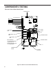


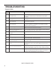
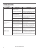
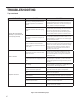
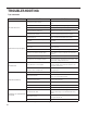
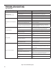
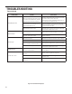
Table Of Contents
- INTRODUCTION
- SPECIFICATIONS
- OPERATION
- ROUTINE MAINTENANCE
- REMOVE AND INSTALL THE CHASSIS
- R-410A SEALED SYSTEM REPAIR
- COMPONENT TESTING
- Hermetic Components Check
- Reversing Valve Description And Operation
- Testing The Reversing Valve Solenoid Coil
- Checking The Reversing Valve
- Replace The Reversing Valve
- Touch Test Chart : To Service Reversing Valves
- Compressor Checks
- Compressor Replacement
- Fan Motor
- Capacitors
- Heating Element
- Drain Pan Valve
- Testing the User Interface and Electronic Control Board
- Thermistors Description
- Electronic Control Board Identification
- Replace the Electronic Control Board
- Replace the User Interface
- TROUBLESHOOTING
- WIRING DIAGRAMS
- PARTS CATALOG
- Available Accessories

68 PB
TROUBLESHOOTING
COMPLAINT CAUSE SOLUTION
Fan motor does not run.
Inoperative system button
Test button & replace user interface if inopera-
tive
Broken, loose or incorrect wiring Refer to applicable wiring diagram
Open capacitor Test capacitor & replace if inoperative
Fan speed button defective Replace user interface if inoperative
Inoperative fan motor
Test fan motor & replace if inoperative (be sure
internal overload has had time to reset)
Does not cool or only cools slightly
Undersized unit Refer to industry standard sizing chart
Indoor ambient thermistor open or
shorted
See diagnostic codes and replace thermistor if
needed.
Dirty lter Clean as recommended in Owner’s Manual
Dirty or restricted condenser or evapo-
rator coil
Use pressure wash or biodegradable cleaning
agent to clean
Poor air circulation Adjust discharge louvers. Use high fan speed
Fresh air or exhaust air door open
Close doors. Instruct customer on use of this
feature
Low capacity - undercharge Check for leak & make repair
Compressor not pumping properly
Check amperage draw against nameplate. If not
conclusive, make pressure test
Unit does not run
Fuse blown or circuit tripped
Replace fuse, reset breaker. If repeats, check
fuse or breaker size. Check for shorts in unit
wiring & components
Loose or disconnected wiring control
board or other components
Check wiring & connections. Reconnect per
wiring diagram
Evaporator coil freezes up
Dirty lter Clean lter (see Routine Maintenance)
Restricted air ow
Check for dirty or obstructed coil. Clean coil
(refer to routine Maintenance)
Inoperative thermistor
Check Diagnostic Codes. Check Thermstors and
replace as necessary.
Short of refrigerant De-ice coil & check for leak
Inoperative fan motor Test fan motor & replace if inoperative
Partially restricted capillary tube De-ice coil. Replace capillary tube
Compressor runs continually & does
not cycle off
Excessive heat load
Unit undersized. Test cooling performance &
replace with larger unit if needed. See sizing
chart.
Restriction in line
Check for partially iced coil & check tempera-
ture split across coil
Thermistor shorted Replace thermistor or electronic control board
Tips continued
Figure 716 (Troubleshooting Tips)