
Trim Kit Installation Instructions


INSTRUCTION SHEET
©2021 Electrolux Home Products, Inc. Instruction Sheet A00343906 9.30.21
15
Top Trim Attachment
NOTE
You will need a step ladder to
install top trim components.
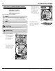
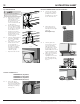
22. a. Remove the front outer
hinge screws, common
on both sides of the
dual installation, as well
as the front two 4H
screws that fasten the 1H
Tie Bar (Fig. 21).
b. Roll the dual installation
into the cabinet, roughly
of the way in, ensuring
the product is centered
in the cabinet cutout.
c. Install the top trim by
fastening four 4H screws
along the base of the
trim with a
5
/
16
” socket
wrench (Fig. 22).
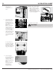
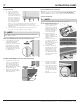
23. a. Slide the dual installation
into place, and make
sure it is center inside
the cabinets.
b. Drill
1
/
8
” pilot holes and
fasten two 3H screws
on the right side of
the Top Trim (one screw
per side for Collared
top trim) with a Phillips
screwdriver to the
cabinets (Fig. 23).
c. Repeat for the left side.
Fig. 21
Fig. 23
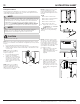
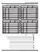
TRMKTEZ2FL75 (Frigidaire)
TRMKTEZ2LV79 (Frigidaire)
TRMKTEZ2FL79 (Frigidaire)
TRMKTSS2FL79 (Electrolux)
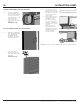
Side Trim Installation For:
24. a. Place side trims in
position by dropping
them over the placement
screw as seen in Fig. 21
and fitting over the top
trim (Fig. 24).
Fig. 24
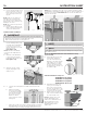
Electrolux TRMKTSS2LV84 Side Trim Installation
25. a. Slide the left Side Trim
into place by carefully
guiding the Side Trim
Attachment slots. Fig. 25
shows an inside view.
Fig. 25
b. Fasten 2H screws to
the top trim (Fig. 26)
and repeat for the right
hand side.
Hand tighten only!
Fig. 26
26. a. Carefully place the
Toe Kick slots over the
4 Leveler Assembly
Tabs. The first Leveler
Assembly tab is circled
in Fig. 27, the second
and third tabs are circled
in Fig. 28, and the fourth
tab is circled in Fig. 29.
b. Adjust the Toe kick until
the magnets are
engaged to the Leveler
Assembly and the Toe
Kick is resting vertically
in place.
Fig. 27
Fig. 29
Fig. 28
Fig. 22