
beverage cooler manual


6
GENERAL OPERATION
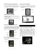
DELIVERY HOSE ARRANGEMENT
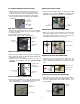
• Insert the clear hose (15) (delivery hose) into the hose
routing clips (8) attached to the door panel. Once the
hoses are properly secured, the CO
2
canister valve can
now be opened.
(15) CLEAR HOSE
(8) HOSE
ROUTING CLIPS
DOOR PANEL
CONNECTIONS
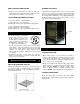
SETTING THE TEMPERATURE CONTROL
The temperature control is located on the back side of the
beverage cooler. The temperature is factory preset for
satisfactory storage temperature. However, the
temperature control is adjustable to provide a range of
temperatures for your personal satisfaction. If a colder
temperature is desired, turn the control shaft of the cold
control clockwise using the tip of the screwdriver as shown
in the diagram below. To set the cold control to “OFF”
position, turn the control shaft counter-clockwise until it
stops. Allow several hours for the temperature to stabilize
between adjustments.
CLEAR HOSE TO DOOR PANEL CONNECTION
• Place the supplied rubber washer (17) inside the hex nut
on the other end of the clear hose (15) (beverage delivery
line) and attach to shank protruding from the door panel
(15) CLEAR HOSE
DOOR PANEL
COUPLER TO KEG INSTALLATION
• Align lug locks on tap head with lug housing on top of keg
and insert the tap head.
• Turn the tap head handle ¼ turn clockwise. The tap head
is now secured to the keg.
• Pull the tap handle out and push down to open the port in
the keg.
KEG TO CABINET INSTALLATION
• Place the keg next to the CO
2
canister (19) inside the
cabinet as shown.
(19) CO2
ANISTER C
KEG
CO
2
CANISTER TO CABINET INSTALLATION
• Place the CO
2
canister (19) with the regulator (13) inside
the CO
2
Canister Bracket (4) in the cabinet. It is important
that the canister be kept in an upright position to operate
efficiently. Fasten the canister securely in place using the
4” long carriage bolt (6) and wing nut (7) supplied with this
unit.
(19) CO
2
CANISTER
(6) 4” LONG
CARRIAGE BOLT
(7) WING NUT
(13)
REGULATOR
(4) CO
2
CANISTER
BRACKET