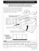
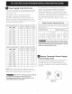
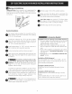
iNSTALLATiON AND SERVICE MUST BE PERFORMED BY A QUALiFiED iNSTALLER. iMPORTANT: SAVE FOR LOCAL ELECTRICAL iNSPECTOR'S USE. READ AND SAVE THESE iNSTRUCTiONS FOR FUTURE REFERENCE. For existing 29" (73.7 cm) cutout wide opening, you must call the Service Center for optional thinner side panels. Also you must prepare the countertop edge as shown in the "Countertop Preparation" section (see page 8). I 30" Min. (76.2 cm) Min. 30" Min. (see Note 3) (76.2 cm) Min.
NOTES: O Do not pinch the power supply cord between the range and the wall. Do not seal the range to the side cabinets. 24" (61 cm) minimum clearance between the cooktop and the bottom of the cabinet when the bottom of wood or metal cabinet is protected by not less than 1/4" (0.64 cm) flame O1 retardant millboard covered with not less than No. 28 MSG sheet metal, 0.015" (0.4 mm) stainless steel, 0.024" (0.6 mm) aluminum, or 0.020" (0.5 mm) copper. 30" (76.
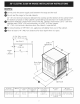
To avoid breakage: manipulate O Do NOT handle or the unit by the cooktop glass. he counter-top around should leveled (see hatched areathe on cut-out illustration 1). be flat and Before installing the unit, measure the heights of the two (2) cabinet sides (H1-4), front and back (see illustration 1) from the floor to the top of the counter.
latest edition, or with local codes in United States and with CAN/CSA-Z240 MH in Canada. important Notes to the Installer 1. Read all instructions contained in these installation 2. 3. 4. instructions before installing range. Remove all packing material from the oven compartments before connecting the electrical supply to the range. Observe all governing codes and ordinances. Be sure to leave these instructions with the consumer.
Power Supply Cord Kit (U.S.A.) The user is responsible for connecting the power supply cord to the connection block located behind the back panel access cover. This appliance may be connected by means of permanent "hard wiring "; flexible armored or nonmetallic shielded copper cable (when local code allow it) or by means of a power supply cord kit. See chart (on next page) for the minimum wire size (general UL listing, local code may differ).
Electrical Shock Hazard • Electrical ground is required on this appliance. • Do not connect to the electrical supply until appliance is permanently grounded. • Disconnect power to the circuit breaker or fuse box before making the electrical connection. • This appliance must be connected to a grounded, metallic, permanent wiring system, or a grounding connector should be connected to the grounding terminal or wire lead on the appliance. 2.
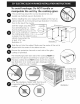
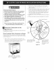
Four Conductor (mobile homes) Wire Connection to Range 1. Remove the 3 screws at the lower end of the rear wire cover, then raise the lower end of the rear wire cover (access cover) upward to expose range terminal connection block (see figure 3). 2. Remove the 3 loose nuts (after you remove the rubber band) on the terminal block using a 3/8"(0,95 cm) nut driver or socket. 3. Remove the ground strap from the terminal block and from the appliance frame. 4.
m Where local codes DO NOT permit connecting the appliance-grounding conductor to the neutral (white) wire, or if connecting to 4-wire electrical system (see Figure 7): 1. Disconnect the power supply. 2. Separate the green (or bare copper) and white appliance cable wires. 3. In the circuit breaker, fuse box or junction box: a) Connect the white appliance cable wire to the neutral (white) wire. b) Connect the 2 black wires together. c) Connect the 2 red wires together.
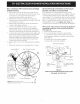
Range Installation Important Note: Door removal is not a requirement for installation of the range, but is an added convenience, Refer to the Use and Care Guide for oven door removal instructions. Position range in front of the cabinet opening. Make sure that the glass which overhangs the countertop clears the countertop. If necessary, raise the unit by lowering the leveling legs.
LeveJing Clean-When the oven is set for a self-cleaning cycle, the upper element should become red during the preheat portion of the cycle. After reaching the self-cleaning temperature, the lower element will become red. the Range Level the range and set cooktop height before installation in the cut-out opening. 1. Install an oven rack in the center of the oven. 2. Place a level on the rack. Take 2 readings with the level placed diagonally in one direction and then the other.
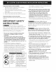
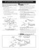
Important Safety 1. Warning To reduce the risk of tipping of the range, the range must be secured to the floor by properly installed anti-tip brackets and screws packed with the range. Those parts are located in a plastic bag in the oven. Failure to install the anti-tip brackets will allow the range to tip over if excessive weight is placed on an open door or if a child climbs upon it. Serious injury might result from spilled hot liquids or from the range itself. 2. 3.
NOTES:
LA INSTALACION Y EL SERVICIO DEBEN SER EFECTUADOS POR UN INSTALADOR CALIFICADO. IMPORTANTE: GUARDE ESTAS INSTRUCClONES PARA USO DEL INSPECTOR LOCAL DE ELECTRIClDAD. LEA Y GUARDE ESTAS INSTRUCClONES PARA REFERENCIA FUTURA. NOTA: Para la abertura amplia de corte de 29" (73,7 cm), tiene que Ilamar al Centro de Servicios y solicitar paneles laterales opcionales. Despejar el reborde ancho de la cocina tal como se muestra en la secci6n "Preparaci6n de la Mesada " (ver p_igina 17). 30" M[n. I - (76.2 cm) M[n.
NOTAS: No pellizque el cord6n el_ctrico entre la estufa y la pared. @ @ 0 No selle la estufa a los armados de lado. Un espacio minimo de 24" (61 cm) entre la superficie de la estufa y el fondo del armario esto cuando el fondo del armario de madera o metal est,1 protegido pot no menos de 1/4" (0.64 cm) de madera resistente al fuego cubierta por una I_qmina met_Slicade MSG, n0mero 28, 0.015" (0.4 ram) de acero inoxidable, 0.024" (0.6 ram) aluminio, 6 0.020" (0.5 mm) de cobre. Un espacio minimo de 30" (76.
Para evitar fractura la unidad de la unidad: sosteniendo la cubierta NO manipule ....... de vidrio. La cubierta alrededor del espacio donde usted instalara su unidad debe de estar plana y nivelada. (Vea el _irea sombreada en la ilustraci0n n0mero 1) Antes de instalar la unidad, mida la altura de los dos (2)lados de los gabinetes (H1-4), frente y parte trasera (vea ilustracion 1) del piso a Io alto de la cubierta.
Notas importantes para el instalador 1.Leatodaslasinstrucciones antesdeinstalarlacocina. 2. Retire todomaterialdeempaquetado delhomoy dela gavetadeentibiadoantesdeconectar elsuministro electricoa lacocina. 3.Observe todocOdigo o reglamento. 4.AsegOrese dedejarestasinstrucciones conelconsumidor Nota importante para el consumJdor Mantenga estas instrucciones con el manual del usuario para futuras referencias.
Estuche de cable dei suministro ei ctrico NOTA: La cocina corrediza electrica viene de fabrica con un agujero de diametro 1 1/8" (2.9 cm) come se muestra en la figura 4. Si un agujero mas largo esta necesario retire la arandela de la pre-cortada. (U.S.A.) El utilizador es responsable de la conexi0n del cable del suministro elOctrico al bloque de conexiOn situado detras del panel de acceso.
i JConexi6n el ctrica tados Unidos). 2. Retire las 3 tuercas desajustadas (luego de haber retirado la banda de caucho) en el bloque terminal con destornillador de tuercas o un casquillo adaptador de 3/8"(0,95 cm). 3. Conecte la parte neutral del cable de bronce de suministro el6ctrico al terminal plateado que se encuentra al centro del bloque terminal y, conecte los otros alambres a los terminales externos.
Conexion del cable de cuatro conductores a la cocina (casas movibles). Conexion el_ctrica directa al cortadrcuito, la caja de fusibles o la caja de empalmes 1. Retire los 3 tornillos de la parte baja de la cubierta del cable trasero, luego levante la cubierta hacia arriba para tener acceso (cubierta de acceso) al bloque de conexiOn del borne terminal (yea figura 3). 2.
Dondelosc6digoslocalesNOpermitanconectarel conductorde puestaa tierradelelectrodom&stico al • El reborde de frente de mostradores moldeados deben tener bordes moldeados a 3/4" (1.9cm) a partir de cada extremidad de la apertura (Figura 8). neutral (blanco), o si est_ conectado con un sistema a 4 alambres (vea figura 7): 1. Desconecte el suministro el_ctrico. 2. Separe el alambre verde (o cobre desnudo) y el alambre blanco del electrodom_stico. 3.
JnstaJadOn de la estufa AsegOrese de que el vidrio que esta colgado sobre la cubierta deje despejada la cubierta. Si es necesario, levante la unidad bajando las patas de nivelaci6n. Nota importante: No es necesario, pero si es conveniente, quitar la puerta para instalar el horno. Consulte las instrucciones para retirar la puerta en la Guia de Uso y Cuidado. Nivele la cocina (vea Nivelaci6n de la estufa). El piso donde se instala la cocina debe estar nivelado.
Nivelaci6n de la estufa Cocer/Bake-Despu_s de poner el homo a 350°F (177°C) para cooer, el element inferior debe ponerse rojo Nivele la estufa y ajuste Ja aJtura de Ja estufa antes de instalarla en la abertura. I. Coloque una parrilla del homo en el centro del horno. 2. Ponga un nivel sobre la parrilla. Tome dos lecturas con el nivel puesto diagonalmente en una direcciOn y despu6s en la otra. Nivele la estufa, si es necesario, ajustando las 4 patas niveladoras con una Ilave de tuercas (Figura 13). 3.
Importante Advertencia que los tornillos no penetren el alambrado el_ctrico o plomeria. Los tornillos provistos pueden utilizarse en madera o concreto. I. Desdoble la plantilla de papel y colOquela plana en el piso con los hordes laterales y el trasero colocados exactamente donde la parte trasera y los lados de la estufa seran colocados cuando sea instalada. (Use el diagrama siguiente para ubicar los soportes si no se dispone de la plantilla). 2.
NOTAS:
UN INSTALLATEUR QUALIFI_: DOlT EFFECTUER L'INSTALLATION ET LE SERVICE IMPORTANT: CONSERVEZ CES INSTRUCTIONS POUR LES INSPECTEURS LOCAUX. USEZ CES INSTRUCTIONS ET CONSERVEZ=LES POUR R#FI_RENCES ULTI_RIEURES. Pour les ouvertures de 29" (73.7 cm) de largeur, vous devez appeler un centre de service pour commander des panneaux lateraux plus minces pour I'installation de la cuisiniere.
NOTES: ONe coincez pas le cordon ONe scellez pas I'appareil Degagement minimum le dessous de I'armoire d'alimentation aux armoires flexible entre le mur et I'appareil. laterales. de 24" (61 cm) entre la plaque de cuisson et le bas de I'armoire en bois ou en metal est protege par un celloderme retardateur du haut Iorsque de flammes d'un O minimum de 1/4" (0.64 cm) recouvert d'une feuille de metal MSG No. 28, d'acier inoxydable d'un minimum de 0.015" (0.4 mm), d'aluminium de 0.024" (0.
Pour 6viter I'appareil les cassures: Ne PAS manipuler par la table de cuisson vitrifi6e. Le comptoir alentour de I'ouverture de decoupage dolt _tre plat eta niveau (voir hachures sur illustration 1). Avant d'installer I'appareil, mesurer les hauteurs des deux (2) c6tes du comptoir (H1-4), avant et arriere (voir illustration 1) du plancher jusqu'au dessus du comptoir. Arasez le 1 Y2"Max. I Mettre I'appareil dessus du (3.8 cm Max.
Notes 1. 2. 3. 4. importantes • Assurez-vous que la tapisserie four peut r_sister a la chaleur _ I'lnstallateur Lisez toutes les instructions contenues dans les Instructions d'installation avant d'installer la cuisiniere. CUlSlnlere. • Avant d'installer la cuisiniere a un endroit recouvert de linoleum ou de tout autre Enlevez tout le materiel d'emballage des compartiments du four avant de connecter I'alimentation electrique a la cuisiniere. Respectez tousles codes et reglements applicables.
Ensemble de cordon d'alimentation raccordement ([=tats-Unis) II incombe _ I'utilisateur de faire raccorder le cordon d'alimentation au bloc de connexion situe derriere le couvercle du panneau arriere.
2. Enlevez (apr6s avoir retir6 la bande elastique), a I'aide d'un tourne-6crou 3/8"(0,95cm), les 3 6crous des bornes du bloc de connexion. 3. Raccordez le neutre du cordon d'alimentation cuivr6 la borne argent6e situ6e au centre du bloc de connexion, et raccordez les autres fils aux bornes ext6rieures. Assortissez les fils et les bornes conform6ment aux couleurs (branchez le fil rouge la borne droite, et le fil noir a la borne gauche). 4.
de raise _ la terre 5. Raccordez leneutre(blanc)ducordond'alimentation Instructions cuivre,a laborneargenteesitueeaucentredu bloc Get appareil est fabriqu6 avec un fil d'alimentation deconnexion, et raccordez lesautresfilsauxbornes neutre (blanc) et un fil de raise a la terre vert ou d6nud6 ext6rieures. Assortissez lesfils et lesbornes reli_ au chassis. conform6ment auxcouleurs(branchez lefil rougea la bornedroite,et lefil noira labornegauche). Raccordez le cable de I'appareil a la bo_te de jonction a 6.
C_qble d'alimentation Les dessus de comptoir au rebord avant moul6 doivent 6tre aplanis de 3/4" (1.9cm) a chaque coin avant de I'ouverture (Figure 8). Fil d6n ud6 \ _---_._ XH__ Fils "-"--._'\.\ /,///_-q-_T" Bo_te.de Jonctlon -_/X Fil blanc _ _"_Con necteur _--_ homologue C_ble de CSA) I'appareil UL II est possible qu'il soit necessaire d'araser de 3/4" (1.9cm) les dessus de comptoir en mosai"que chaque coin avant et/ou d'aplanir le rebord arrondi (Figure 8).
Installation de la cuisiniere Centrez I'appareil devant le centre I'ouverture du comptoir. Note Importante: L'enl_vement de la porte du four n'est pas requis pour I'installation de I'appareil, mais la facilite grandement. R_f_rez-vous au manuel d'utilisation pour conna;tre les _tapes. Assurez-vous que la surface de cuisson vitrifi6e allant par dessus le comptoir est bien plus haute que le comptoir. Si tel n'est pas le cas, levez I'appareil en baissant les pattes de nivellement.
Mise a niveau de la cuisiniere I'expedition. Nous vous suggerons cependant de verifier une fois de plus le fonctionnement des commandes du contr61eur electronique. Referez-vous au Manuel d'utilisation et d'entretien pour le mode de fonctionnement. Suivez les instructions sur les fonctions Mettez Ja cuisini&re de niveau et ajustez Ja hauteur de la table de cuisson avant de J'instaJJer dans Je d&coupage du cornptoir. I. Installez une grille au centre du four. 2. D@osez un niveau a bulle sur la grille.
Instructions de s cudte 1. Depliez le gabarit de papier et placez-le a plat sur le plancher, I'endos et les extremites des c6tes exactement a I'endroit ou I'arriere et les c6tes de la cuisiniere seront places lots de I'installation (utilisez le diagramme ci-dessous pour Iocaliser les supports anti-bascules si le gabarit de papier n'est pas disponible). 2. Tracez sur le plancher I'emplacement des 4 trous de montage indiques sur le gabarit. Pour faciliter I'installation, des trous pilotes d'un 1/2"(1.
NOTES: 36