
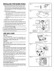
Installation guide
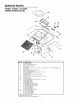


SERVICE PARTS
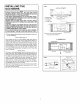
F30WC, F36WC, & F42WC
SERIES RANGE HOOD
21
I
i 12
15
13
4
17
18
11
16
19
<
2
10
KEY NO.
I
2
3
4
5
6
7
8
9
10
I1
I2
I3
I4
I5
I6
I7
I8
I9
20
21
DESCRIPTION
Outlet Box Cover
#8 x 3/8 Sheet Metal Screw*
Bulb Holder with Wires
Light Lens
Screw/Nut Kit (includes 2 - #I0-16 x .500 screws and 2 - #I0-16 sheet metal nuts)
Fan Blade
#6-32 Locking Nuts* (2 Required)
Motor Mounting Bracket
Motor Assembly (includes Key Nos. 6, 7, and 8)
Aluminum Filter
Non-Ducted Filter (purchase separately)
Filter Retainer
#8B x I/4 Hex Head Sheet Metal Screws* (2 Req)
Damper Flap
Damper Bushing
Damper Assembly (includes Key Nos. I3 and I4)
Nameplate (Black)
Nameplate (White)
Nameplate (Biscuit)
2-Speed Motor Switch (Black)
2-Speed Motor Switch (White)
2-Speed Motor Switch (Biscuit)
Light Switch (Black)
Light Switch (White)
Light Switch (Biscuit)
Motor Receptacle with Wires
Louver Cover (Black)
Louver Cover (White)
Louver Cover (Biscuit)
7" Round Duct Plate
Order service parts by "KEY NO."
* Standard Hardware. May be purchased locally.