
Installation guide

3. Electrical Connection to the Range
(U.S.A.)
This appliance is manufactured with the neutral terminal
connected to the frame.
Three Conductor Wire Connection to Range
(The 3-conductor cord or cable must be replaced with a
4-conductor cord or cable where grounding through the
neutral conductor is prohibited in new installations,
mobile homes, recreational vehicles or in other areas
where local codes do not permit neutral grounding)
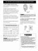
If local codes permit connection of the frame grounding
conductor to the neutral wire of the copper power supply
cord (see Figure 4).
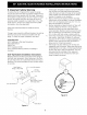
1. Remove the 3 screws at the lower end of the rear
wire cover, then bend the lower end of the rear wire
cover (access cover) upward to expose range
terminal connection block (see Figure 3).
2. Remove the 3 loose nuts (after you remove the
rubber band) on the terminal block using 3/8" nut
driver or socket.
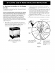
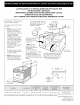
3. Connect the neutral of the copper power supply cord
to the center silver-colored terminal of the terminal
block, and connect the other wires to the outer
terminals. Match wires and terminals by color (red
wires connected to the right terminal, black wires
connected to the left terminal).
4. Replace the 3 nuts on the terminal block (see figure
4).
5. Lower the terminal cover and replace the 3 screws.
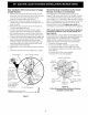
Silver Colored Terminal
Red Wire
Terminal
Block
Black
Wire
BEND REAR WIRE COVER HERE
FOR ACCESS TO TERMINAL BLOCK
Figure 3
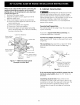
A User Supplied Strain-
relief Must Be Installed
at This Location. To 240 V
Receptacle
Figure 4
1 1/8" (2.9 cm) Dia.
Direct Connection
Hole. Punch Out
Knockout for 1 3/8"
(3.5 cm) Dia. Cord
Kit Hole.
4