
Installation guide

7. Check Operation
Refer to the Owner's Guide packaged with the range for
operating instructions and for care and cleaning of your
range.
Do not touch the elements. They may be
hot enough to cause burns.
Remove all packaging from the oven before testing.
1. Operation of Surface Elements
Turn on each of the four surface elemens and check to
see that they heat. Check the surface element indicator
light(s), if equipped.
2. Operation of Oven Elements
The oven is equipped with an electronic oven control. Each
of the functions has been factory checked before shipping.
However, it issuggested that you verify the operation of
the electronic oven controls once more. Refer to the
Owner's Guide for operation. Follow the instructions for the
Clock, Timer, Bake, Broil, Convection (some models) and
Clean functions.
Bake-After setting the oven to 350°F (177°C) for baking,
the lower element in the oven should become red.
Broil-When the oven is set to BROIL, the upper element
in the oven should become red.
Clean-When the oven is set for a self-cleaning cycle, the
upper element should become red during the preheat
portion of the cycle. After reaching the self-cleaning
temperature, the lower element will become red.
Convection (some models)-When the oven is set to
CONV. BAKE/ROAST at 350°F (177°C), both elements
cycle on and off alternately and the convection fan will
turn. The convection fan will stop turning when the oven
door is opened during convection baking or roasting.
Warmer Drawer (some models)-Set the control knob
to HI and check to see the drawer is heating.
When All Hookups are Complete
Make sure all controls are left in the OFFposition.
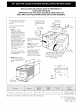
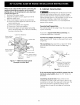
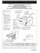
Model and Serial Number Location
The serial plate is located on the oven front frame
behind the oven door (some models) or behind the
drawer (some models).
When ordering parts for or making inquiries about your
range, always be sure to include the model and serial
numbers and a lot number or letter from the serial plate
on your range.
Before You Call for Service
Read the Avoid Service Checklist and operating
instructions in your Owner's Guide. It may save you time
and expense. The list includes common occurrences that
are not the result of defective workmanship or materials
in this appliance.
Refer to the warranty and service information in your
Owner's Guide for our phone number and address.
Please call or write if you have inquiries about your
range product and/or need to order parts.
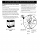
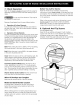
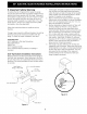
8. Optional Anti-Tip Screws
(Lift-top Models Only)
Raisethe lift-up cooktop and support it with cooktop
supprot rod. Drill 1/8" (0.3 cm) diameter pilot holes into
countertop using holes in upper side panels as a
template. Fasten the upper side panels to the countertop
with screws provided in a plastic bag in the oven.
Anti-Tip
g Screws
2 on Each Side
Figure 10
8