
Installation guide


ELECTRICAL CONNECTIONS
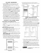
FOR A 3-WIRE SYSTEM
I
ELECTRICLaundry Center
1, Remove the screw securing the
terminal block access cover to the
rear panel and remove cover.
2, Install a U.L approved strain relief
connector in the entry hole on the
back panel.
3, Insert a NEMA 10-30 Type SRDI,
Ui. approved power cord
through the strain relief,
4, Attach the power cord neutral (central wire) conductor to
the silver colored center terminal on the terminal block,
Tighten the screw securely.
6, Attach the white (neutral) wire from the power cord and the
green ground wire from the appliance harness to the silver-
colored center terminal on the terminal block. Tighten the
screw securely.
Green Ground
Screw
/ Silver Terminal
Conductor
(Cord)
Terminal Block
Green Ground
Wire
"White
_Black
7, Attach the red and black wires from the power cord to the
outer brass-colored terminals on the terminal block. Tighten
both screws securely.
8, Tighten the screws securing the cord restraint firmly against
the power cord,
9, Reinstall the terminal block access coven
5,Attach the remaining two power cord outer conductors to
the outer brasscolored terminals on the terminal block,Tighten
both screw securely,
&Tighten the screws securing the cord restraint against
the power cord,
7, Reinstall the terminal accesscover
ELECTRICAL CONNECTIONS
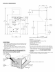
FOR A 4-WIRE SYSTEM
I
ELECTRICLaundry Center
1, Remove the screw securing the
terminal block accesscover to the
rear panel and remove cover.
2, Install a U.L approved strain relief
connector in the entry hole on the
back panel,
3, Remove the green neutral ground wire
from the green ground screw located above the termial
block,
4, Insert a NEMA 14-30 Type STor SRDT,U,L, approved power
cord through the strain relief,
5, Attach the green power cord ground wire to the cabinet
with the green ground screw
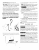
INSTALLATION
1, Run some water from the hot and cold faucets to flush the
water lines and remove particles that might clog up the
water valve screens.
2, Check inlet hoses to ensure the rubber washers are installed
in each end,
3, Carefully connect the inlet hoses to the water valve (on the
left side of the washer cabinet), tic hten by hand, then tighten
another 2/3 turn with pliers,
_DO NOT CROSS THREAD OR OVERTIGHTEN
THESECONNECTIONS.
4, Determine which water faucet is the HOT water faucet and
carefully connect the bottom inlet hose to the HOT water
faucet, tighten by hand, then tighten another 2/3 turn with
pliers, Carefully connect the top inlet hose to the COLD
water faucet, tighten by hand, then tighten another 2/3 turn
with pliers.
DO NOT CROSS THREAD OR OVERTIGHTEN
ECTIONS. Turn the water on and check for leaks
at both connections,
5, Carefully move the laundry center to its final location,
6, ]o ensure the laundry center is level and solid on all four
legs, tilt the laundry center forward so the rear legs are
off the ground. Gently set the laundry center back down to
allow the rear legs to self adjust. Placea level on top of the
washer Check it side to side, then front to back. Screw the
front leveling legs up or down to ensure the laundry center
is resting solid on all four legs (no rocking of the laundry
center should exist).
NOTE: Keep the leg extension at a minimum to prevent
excessive vibration.
7