
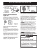
Installation Guide


2
30" ELECTRIC RANGE INSTALLATION INSTRUCTIONS
9”
6”
2½”
3”
C
L
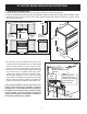
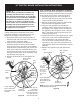
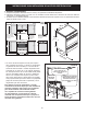
1. Clearances and Dimensions
a. Provide adequate clearances between the range and adjacent combustible surfaces.
b. Location—Check location where the range will be installed. Check for proper electrical supply and the stability of fl oor.
c. Dimensions that are shown must be used. Given dimensions provide minimum clearance. Contact surface
must be solid and level.
* 30" minimum clearance between the top of the
cooking surface and the bottom of an unprotected
wood or metal cabinet; or 24 " minimum when
bottom of wood or metal cabinet is protected by
not less than ¼" fl ame retardant millboard covered
with not less than no. 28 MSG sheet steel, 0.015"
stainless steel, 0.024" aluminum or 0.020" copper.
The minimum clearance is 0" for the rear of the
range. Follow all dimension requirements provided
above to prevent property damage, potential fi re
hazard, and incorrect countertop and cabinet cuts.
Avoid locating cabinet storage space above the
surface units to eliminate the possibility of cabinets
catching on fi re, or personal burns from reaching for
the cabinets over the heated units. If cabinet storage
is to be provided, risk can be reduced by installing a
range hood that projects horizontally a minimum of
5" beyond the bottom of the cabinets.
BACK
VIEW
All dimensions for
electrical outlet location are
maximum.
Cubed area shows
where the electrical
outlet must be installed
for the range to be
fl ush to the wall.
Terminal
Block
Location
1”
30” Minimum*
30”
Minimum to
wall on either
side of range
above 36” height.
36”
18”
Minimum to
cabinets on
either side
of range
30 1/8”
25” Max.
13”
Maximum depth
for cabinets
above range top.
0” clearance below cooking top and at rear of range
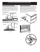
Typical cabinet installationFront
view
Side
view
Maximum
Door open
29
7
/
8
"
46"
26"
36
3
/
8
"
±
1
/
4
"