
Installation Guide


8
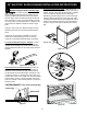
30" ELECTRIC SLIDE-IN RANGE INSTALLATION INSTRUCTIONS
Min.
Cutout
Width
Formed or tile countertop
trimmed ¾" (1,9 cm) back at
front corners of countertop
opening.
Figure 7
6.
Cabinet Construction
6.1
To eliminate the risk of burns
orrebyreachingoverheatedsurfaceunits,donot
have cabinet storage space above the range. If there
is cabinet storage space above range, reduce risk
by installing a range hood that projects horizontally
a minimum of 5" (12,7 cm) beyond the bottom of the
cabinet.
6.2
Countertop Preparation
• Thecooktopsidesoftherangetoverthecutout
edge of your countertop.
• Ifyouhaveasquare nish (at) countertop, no
countertop preparation is required. Cooktop sides lay
directly on edge of countertop.
• Formed front-edged countertops must have
moldededgeshavedat3/4"(1,9cm)fromeach
front corner of opening (Figure 7).
• Tile countertops may need trim cut back 3/4" (1,9
cm) from each front corner and/or rounded edge
attened(Figure7).
• If the existing cutout width is greater than 30
1/16" (76,4 cm), reduce the ¾" (1,9 cm) dimension.
• Countertop must be level. Place a level on the
countertop,rstsidetoside,thenfronttoback.Ifthe
countertop is not level, the range will not be level. The
oven must be level for satisfactory baking results.
Cooktopsidesofrangetoveredgesofcountertop
opening
1. Be sure that no power is supplied on the cable from
residence.
2. DO NOT remove the grounding strap for 3-wire
installation.
3. In the circuit breaker, fuse box or junction box:
a) Connect the green (or bare copper) wire, the white
appliance cable wire, and the neutral (white) wire
together.
b) Connect the 2 black wires together.
c) Connect the 2 red wires together.
Where local codes DO NOT permit connecting
the appliance-grounding conductor to the neutral
(white) wire, or if connecting to 4-wire electrical
system (see Figure 6):
1. Be sure that no power is supplied on the cable
from residence.
2. Remove the grounding strap from the terminal
block and from the appliance frame.
3. In the circuit breaker, fuse box or junction box:
a) Connect the white appliance cable wire to the
neutral (white) wire.
b) Connect the 2 black wires together.
c) Connect the 2 red wires together.
d) Connect the green (or bare copper) grounding
wire to the grounding wire of the circuit breaker,
fuse box or junction box.
Figure 5 - 3-Wire (Grounded Neutral) Electrical
System (Example: Junction Box)
Cable from Residence
Junction
Box
White Wire
U.L.-listed Conduit
Connector (or CSA
listed)
Cable from
Appliance
Green
(or Bare Copper)
Wire
Red
Wires
Neutral
(white) Wire
Black
Wires
U.L.-listed Conduit
Connector (or CSA
listed)
Figure 6 – 4-Wire Electrical System
(Example: Junction Box)
Cable from Residence
Black
Wires
Junction
Box
White Wire
Cable from
Appliance
Green (or Bare
Copper) Wire
Red
Wires
White Wire
Green (or Bare
Copper) Wire