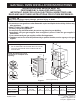
GAS WALL OVEN INSTALLATION INSTRUCTIONS INSTALLATION AND SERVICE MUST BE PERFORMED BY A QUALIFIED INSTALLER. IMPORTANT: SAVE FOR LOCAL ELECTRICAL INSPECTOR'S USE. READ AND SAVE THESE INSTRUCTIONS FOR FUTURE REFERENCE. If the information in this manual is not followed exactly, a fire or explosion may result causing property damage, personal injury or death. FOR YOUR SAFETY: — Do not store or use gasoline or other flammable vapors and liquids in the vicinity of this or any other appliance.
GAS WALL OVEN INSTALLATION INSTRUCTIONS Important Notes to the Installer • 1. Read all instructions contained in these installation instructions before installing the appliance. 2. Remove all packing material and literature from the oven and broiler compartments before connecting gas and electric supply. 3. Observe all governing codes and ordinances. 4. Be sure to leave these instructions with the consumer. 5. For operation at 2000 ft.
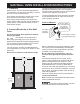
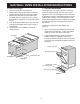
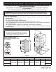
GAS WALL OVEN INSTALLATION INSTRUCTIONS 1. Carpentry The wall receptacle should be located in the cabinet beneath the installation cutout. The receptacle should be easily accessible for service and removal of power from appliance (see Figure 2) The wall receptacle and circuit should be checked by a qualified electrician to make sure the receptacle is properly grounded. Refer to Figure 1 for the dimensions applicable to your appliance, and the space necessary to receive the oven. Corners must be square.
GAS WALL OVEN INSTALLATION INSTRUCTIONS 3. Alternate construction 4. Adjusting Oven Height Installation Instructions for installing a 1½ cavity oven into an existing 2 cavity opening with dimensions 42-1/8" height by 22 ½" Width. Remove and lay aside the lower vent decorative trim that is taped to the side or to the top of the oven. The decorative trim will be fastened to the lower front of the oven after it has been installed in the cabinet.
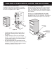
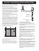
GAS WALL OVEN INSTALLATION INSTRUCTIONS 5. Cabinet Installation To adjust oven height: 1. Lay oven on its back (see Figure 6). 2. Remove the 3 screws that fasten the side extension panel to the bottom sides of the oven. 3. Move each panel down to the position that increases the oven height to fit your opening. Each position changes oven height approximately ½". 4. Line up the appropriate holes in the side extension panels and sides of the oven. Put the 3 screws back. 5. Proceed with oven installation.
GAS WALL OVEN INSTALLATION INSTRUCTIONS 6. Provide an Adequate Gas Supply 7. Connection to Gas (see Figure 9) Important: Read these instructions carefully before connecting this unit to a gas supply. Shut-Off Valve The units covered in these instructions are designed to operate on natural gas at 4" of manifold pressure or on LP gas at 10" of manifold pressure.
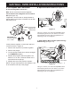
GAS WALL OVEN INSTALLATION INSTRUCTIONS 8. LP/Propane Gas Conversion B. Adjust Oven Burner Orifice (see Figure 11) A. Pressure Regulator Conversion Pin Note: Do not remove the Pressure Regulator. Nat. Convert the Pressure Regulator for use with LP Gas (see Figure 10). Air Shutter L.P. Orifice If applicable, remove broiler or storage drawer by pulling drawer out to stops. Lift drawer front to clear stops and pull out.
GAS WALL OVEN INSTALLATION INSTRUCTIONS 9. Natural Gas Conversion For Natural Gas, the air shutter should be approximately half open. For LP Gas, the air shutter nearly full open. Convert the Pressure Regulator for use with Natural Gas (see Figure 10) Too much air will cause the flame to lift away from the burner. Too little air will cause the flame to turn yellow at the outer edges and soot to form. A. Remove the cap from the pressure regulator. B. Remove the plunger. C.
GAS WALL OVEN INSTALLATION INSTRUCTIONS 11. Check Operation Before You Call for Service Refer to the Use and Care Guide packaged with the wall oven for operating instructions and for care and cleaning of your appliance. Read the Avoid Service Checklist and operating and cleaning instructions in your Use and Care Guide. Do not touch the oven burners. They may be hot enough to cause burns. Check to make sure the house fuse or circuit breaker for your wall oven is not blown or open. 1.
HORNO DE GAS DE PARED - INSTRUCCIONES DE INSTALACIÓN LAS TAREAS DE INSTALACIÓN Y SERVICIO DEBERÁN SER REALIZADAS POR UN INSTALADOR CUALIFICADO. IMPORTANTE: CONSERVAR PARA USO POR PARTE DE LOS INSPECTORES DE ELECTRICIDAD. LEA Y CONSERVE ESTAS INSTRUCCIONES PARA SU CONSULTA FUTURA WARNING: Si no se sigue al pie de la letra la información de esta guía, se puede producir un incendio o una explosión, lo cual causaría daños a la propiedad, lesiones personales o la muerte.
HORNO DE GAS DE PARED - INSTRUCCIONES DE INSTALACIÓN Notas importantes para el instalador • 1. Lea todas las instrucciones contenidas en estas instrucciones de instalación antes de instalar el dispositivo. 2. Retire todo el material de embalaje y papel impreso de los compartimentos de horno y la asadera antes de conectar el gas y la corriente eléctrica. 3. Observe todas las normas aplicables. 4. Asegúrese de dejar estas instrucciones al consumidor. 5.
HORNO DE GAS DE PARED - INSTRUCCIONES DE INSTALACIÓN 1. Carpintería La toma de la pared deberá estar situada en el armario bajo el troquelado de instalación. La toma deberá ser fácilmente accesible para tareas de servicio y desconexión de la corriente eléctrica del dispositivo (ver Figura 2). Consulte las dimensiones de su dispositivo y el espacio necesario para acomodar el horno en la Figura 1. Las esquinas deberán ser cuadradas.
HORNO DE GAS DE PARED - INSTRUCCIONES DE INSTALACIÓN 3. Construcción alternativa 4. Ajuste de la altura del horno Instrucciones de instalación para instalar un horno con cavidad de 1½ en una abertura existente de 2 cavidades con dimensiones de 42-1/8" de altura por 22 ½" de anchura. Retire y deje a un lado la moldura decorativa del orificio de ventilación inferior que está pegada al lateral o a la parte superior del horno.
HORNO DE GAS DE PARED - INSTRUCCIONES DE INSTALACIÓN 5. Instalación del armario Para ajustar la altura del horno: 1. Coloque el horno sobre la parte posterior (ver Figura 6). 2. Retire los tres tornillos que ajustan el panel lateral de extensión a los laterales inferiores del horno. 3. Mueva cada panel hacia abajo a la posición que aumenta la altura del horno para ajustarse al espacio abierto. Cada posición cambia la altura del horno aproximadamente en ½". 4.
HORNO DE GAS DE PARED - INSTRUCCIONES DE INSTALACIÓN 7. Conexión al gas (ver Figura 9) 6. Proveer un suministro de gas adecuado Importante: Lea atentamente estas instrucciones antes de conectar esta unidad a un suministro de gas. Válvula de desconexión Las unidades a las que se refieren estas instrucciones están diseñadas para funcionar con gas natural con una presión de 4" en el colector o gas LP con 10" de presión en el colector.
HORNO DE GAS DE PARED - INSTRUCCIONES DE INSTALACIÓN 8. Conversión a gas LP/Propano B. Ajuste el orificio del quemador del horno (ver Figura 11) A. Conversión del regulador de presión Nota: No retire el regulador de presión. Espiga Convertir el regulador de presión para uso con gas LP (ver Figura 10). Nat. L.P. En su caso, retire la asadera o cajón de almacenamiento tirando del cajón hasta los topes. Levante el frontal del cajón para quitar los topes y sáquelo.
HORNO DE GAS DE PARED - INSTRUCCIONES DE INSTALACIÓN 9. Conversión de gas natural Para gas natural, el obturador de aire deberá estar abierto aproximadamente a la mitad. Para gas LP, el obturador de aire deberá estar casi totalmente abierto. Convertir el regulador de presión para uso con gas natural (ver Figura 10). Un exceso de aire hará que la llama se separare del quemador. Demasiado poco aire hará que la llama se amarillee en los bordes exteriores y se forme hollín. A.
HORNO DE GAS DE PARED - INSTRUCCIONES DE INSTALACIÓN 11. Comprobación del funcionamiento Antes de solicitar servicio técnico Lea la Lista de comprobación y las instrucciones de limpieza y funcionamiento en su Guía de uso y cuidado. Consulte la Guía de uso y cuidado incluida con el horno de pared para ver las instrucciones de funcionamiento y el cuidado y limpieza de su dispositivo. Compruebe que el fusible de la toma de corriente o el cortacircuitos del horno no estén fundidos o abiertos.
INSTRUCTIONS DE MONTAGE DU FOUR À GAZ MURAL L’INSTALLATION ET L’ENTRETIEN DOIVENT ÊTRE RÉALISÉS PAR UN INSTALLATEUR QUALIFIÉ. IMPORTANT : CONSERVEZ CES INSTRUCTIONS EN PRÉVISION D’UN USAGE ÉVENTUEL PAR L’INSPECTEUR EN ÉLECTRICITÉ DE VOTRE LOCALITÉ. VEUILLEZ LIRE ET CONSERVER CES INSTRUCTIONS POUR VOUS Y REPORTER ULTÉRIEUREMENT.
INSTRUCTIONS DE MONTAGE DU FOUR À GAZ MURAL Notes importantes à l'intention de l'installateur • Note importante à l'intention du consommateur Ne pas ranger d’articles pouvant intéresser les enfants dans les armoires situées au-dessus de l’appareil. Sinon, les enfants peuvent subir de graves brûlures ou blessures s'ils grimpent sur l'appareil pour attraper ces articles.
INSTRUCTIONS DE MONTAGE DU FOUR À GAZ MURAL 1. Travaux de menuiserie La prise de courant murale doit se retrouver dans l'armoire, en dessous de la découpe de montage. Elle doit être facile d'accès pour l'entretien et pour débrancher l'appareil électroménager (voir la figure 2). Se reporter à la figure 1 pour les dimensions de votre appareil électroménager et les mesures d'espace nécessaire pour accueillir le four. Les coins doivent être d'équerre.
INSTRUCTIONS DE MONTAGE DU FOUR À GAZ MURAL 3. Autre méthode de construction 4. Réglage de la hauteur du four Instruction de montage d'un four à 1½ cavité dans une ouverture à 2 cavités dont les dimensions représentent 107 cm (42⅛ po) de haut par 57,150 cm (22½ po) de largeur. Récupérer la garniture décorative collée sur le côté ou sur le dessus du four et la mettre de côté. La garniture sera fixée au bas sur le devant du four une fois installé dans son armoire.
INSTRUCTIONS DE MONTAGE DU FOUR À GAZ MURAL 5. Montage de l'armoire Réglage de la hauteur du four : 1. Coucher le four sur le dos (voir figure 6). 2. Retirer les 3 vis qui retiennent le panneau de rallonge latéral sur les côtés du bas du four. 3. En déplaçant chaque panneau vers le bas, trouver le positionnement qui allonge la hauteur du four pour cadrer dans l'ouverture. Chaque position ajuste la hauteur du four d'environ 12,70 mm (½ po). 4.
INSTRUCTIONS DE MONTAGE DU FOUR À GAZ MURAL 7. Connection to Gas (see Figure 9) 6. Assurer un niveau adéquat d'approvisionnement en gaz Robinet d'arrêt Important: Lire soigneusement ces instructions avant de raccorder le four à un approvisionnement en gaz. Ces instructions concernent les fourneaux conçus pour fonctionner au gaz naturel à pression d'admission de 10 cm H2O (de colonne d'eau [W.C.
INSTRUCTIONS DE MONTAGE DU FOUR À GAZ MURAL 8. Conversion au propane B. Réglez orifice de brûleur du four (voir Figure 11) A. Conversion du régulateur de pression Goupille Remarque: Ne pas retirer le régulateur de pression. Nat. Convertir le régulateur de pression au propane (voir Figure 10). Obturateur d'air Le cas échéant, enlever la grille ou le tiroir de rangement en le tirant jusqu'aux butées d'arrêt. Soulever le devant du tiroir au dessus des butées et tirer. Joint d'étanchéité L.P.
INSTRUCTIONS DE MONTAGE DU FOUR À GAZ MURAL 9. Conversion au gaz naturel Pour les installations au gaz naturel, l'obturateur d'air doit être environ semi-ouvert Pour les installations au propane, presque complètement ouvert. Convertir le régulateur de pression au gaz naturel (voir Figure 10) Trop d'air permet à la flamme de s'élever au-dessus du brûleur. Trop peu d'air produit une flamme au pourtour jaunâtre et forme de la suie. A. Retirer le bouchon du régulateur de pression. B. Retirer le piston. C.
INSTRUCTIONS DE MONTAGE DU FOUR À GAZ MURAL 11. Check Operation Avant de contacter le réparateur Se reporter au manuel d'entretien et d'utilisation expédié avec le four mural pour le mode d'emploi et pour le nettoyage et l'entretien de l'appareil électroménager. Lire soigneusement la liste de contrôle pour éviter les demandes de réparation et le mode d'emploi et de nettoyage dans le manuel d'entretien et d'utilisation. Éviter de toucher aux brûleurs de four.