
Installation Instructions


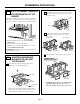

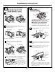


INSTALLATION OVERVIEW
B1. Prepare Rear Wall
B3. Attach Moun tin g Plate to Wall
B4. Prepare Top Cabinet
B5. Adjust Blower
B6. Mount the Microwave Oven
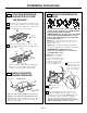
IMPORTANT NOTES:
• Make sure th e screws for th e
blower motor and blower plate
are securely tighten ed when
they are rein stalled. Th is will
help to preven t excessive
vibration.
•
been properly routed and secured,
and th at the wires are not pinch ed.
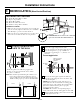
Remove and save th e screw th at holds the blower
plate to th e microwave. Lift off the blower plate.
Back of
M icrow ave
Installation Instructions
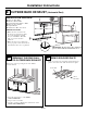
PREPARING THE REAR WALL
FOR OUTSIDE BACK EXHAUST
B1.
You need to cut an opening in th e rear wall for
outside exh aust.
• Read th e instructions on th e REAR
WALL TEMPLATE.
• Tape it to the rear wall.
• Cut the opening, following the instructions of the
REAR WALL TEMPLATE.
B2.
OUTSIDE BACK EXHAUST (Horizontal Duct)
B
Blow er Plate
REMOVE BLOWER PLATE
B2. Remove Blower Plate
3/8" TO EDGE
NO
TE
: IT IS VE
RY IMPOR
TANT TO
READ A
ND FOLL
OW THE DIRECTIONS
IN THE IN
STALLATION INSTRUCTIONS
BEFORE PROCEEDING WITH THI
S
RE
AR W
ALL TEMPLATE.
T
his Rear Wall
T
emplate serves to positi
on the bottom
mounting plate a
nd to locate the horiz
ont
al exhaust
outlet.
1.
Us
e a level to
check that the template is positioned
accurat
ely.
2. Loc
ate and mark at least one stud on the
left
or
right side of the centerl
ine.
I
t is import
ant
t
o
use at leas
t
on
e wood
screw moun
ted firmly in a stud
to support
the weight
of
the microwave. Mark two a
dditional, e
v
enly spaced
locations for the supplied toggle bolts.
3. Drill holes in the mark
ed locations.
Wh
ere
there is
a stud, drill a 3/16" hole for wood screws.
For holes
that do not line up with a stud, dr
il
l 5/8" hole
s
f
or
toggle bolts.
DO NOT INST
ALL
THE MOUNTING PLATE
AT THIS TIME.
4.
Remove the tem
plate
from the
rear wall.
5. Review the Installat
ion Instruc
tion boo
k
for your
installation situatio
n.
Locate and
mar
k hol
es to
align with holes in the
mou
nti
ng plate.
IMPO
RTA
NT:
LOCATE AT LEAST ONE
STU
D
ON EITHER SIDE OF
THE CENTERLINE.
MARK TH
E LOCATION FOR
2 AD
D
IT
IO
NAL, EVENLY
SPACED TOGG
LE BOLTS IN THE MOU
NTING PLATE
AREA.
Locate and mar
k holes to align w
ith holes in the
mounting plate.
IMPORTANT:
LOCATE AT LEAST ON
E STUD ON EITH
ER SIDE
OF
THE CENTER
LINE.
MARK THE LOCATION FOR
2 AD
DITI
ONAL, EVEN
LY
SPACED TOGGLE BOLTS IN THE M
OUNTING PLATE
AREA.
Trim the rear wa
ll template alon
g the dotted line.
Trim
the rear
wall templa
te along the
dotted
line.
1
2
"
4
"
Darle vuelta
a la ho
ja para
con
sultar la
ve
r
sión
en Español.
Make sure the motor wiring has
EN-16
3/8"TO
EDG
E
%#76
+10
Ä+(':*#756#&#
26
14+5215+6+10'&1765+&'
4'%1/
/'0&'&&
+/'05+10)4'#5'Ä.
#
&'0#+49+..
&
+5%*#4)'+061*175
'564
7%674'
/
+0+/7/9+&6*4'37+4'&
4'#49#..6'/2.#6'
NOTE: IT IS VERY
IMPORTANT TO
READ AND FO
LLOW
T
HE
DIRECTIONS
IN THE INSTALLAT
ION INSTRU
CTI
ONS
BEFO
RE PR
O
CEEDINGWITH T
HIS
REAR W
A
LL TEMPLAT
E.
T
h
i
s R
ear
Wall Template
s
er
ves
to positio
n
th
e
b
o
ttom
mou
nting plateand
to l
oc
ate th
e horizonta
l ex
haust
out
le
t.
1. Use a le
vel
to
c
heck th
at th
e t
empla
te
is p
ositioned
accu
ratel
y
.
2. Locate
a
ndm
ark at le
as
t o
nestu
d
on thele
ft or
right
s
id
e
o
f the centerlin
e.
016
'
It is impo
rt
ant to use at le
ast
one
wo
od
scre
w
mounted fi
r
mly
in a
s
tud to support th
e weight
ofth
e micr
owave.
M
ar
k
tw
o a
ddi
tional, e
venlyspa
c
ed
locations f
or
th
e
s
upplied toggle bol
t
s.
3. Dr
i
ll h
oles in
th
e marked location
s.Where there is
a
s
tu
d, dr
ill
a 3/16" h
o
l
e
for
woo
d scr
e
w
s.
F
or h
oles
thatdo not lin
e upwith a stud, dril
l 5/8
"
h
ole
s for
to
ggl
e bo
lts.
016
'
DO
NO
T INS
T
A
LL THE
MO
UNTI
N
G
P
L
A
TE
AT T
HIST
IME.
4. Rem
ove the template fromthe
rear wal
l.
5.Re
vie
wthe Installation
Ins
t
ruction bo
ok for y
our
installation s
i
tuat
ion.
Locat
e and m
ar
k holes to ali
gn wi
th holes
in the
mounting
p
late.
IMPO
RTANT:
LOCA
T
E AT LEAST ONE STUD
ON EITHER
SIDE O
F
TH
E CENTERLIN
E
.
MARKTHE LOCATION FOR 2 ADDITIONA
L, EVENLY
SPACED TO
GGLE
BO
LTS
IN THE MO
UN
TING
PLATE
AREA
.
Locate and mar
k holes
to al
i
gn with holes
in the
mountingplate.
IMPORTANT
:
LO
CATE AT LEA
ST ONESTUD ON EITHER SI
DE O
F
TH
E
CENTER
LINE.
MARKTHE LOCATION F
O
R 2 ADDITIONAL, EVENLY
SP
ACEDTO
G
GLE BO
LTS IN
THE MOUNTING
PLATE
AREA
.
Trim the rear wall template along
t
he dotted line.
Trim the
rear
wal
l t
em
plat
e along
t
h
e dotted line.
%
(%76176(14*14+<106#.
1765+&'':*#756
%7
6*
1
.
'6
*4
17)*4'#49#.
.
(
1
4
':*#756#ą
4
12"
4"
Da
r
l
ev
u
eltaa la ho
j
apar
aconsul
tar
la
v
e
r
s
i
ó
ne
nEspañol.
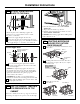
IMPORTANT :Do not remove the cardboard
etween the heat shield and door.
spacers b